
User Guide


COPYRIGHT
©
1999 CANON INC. CANON CLC1120/1130/1150 REV.0 MAR. 1999 PRINTED IN JAPAN (IMPRIME AU JAPON)
13-103
CHAPTER 13 TROUBLESHOOTING
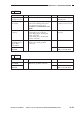
8 E016
Cause
Cleaner blade
reciprocating
motor (M7)
DC driver PCB,
CPU PCB
Action
Check the wiring from
J1028 to the motor; if
normal, replace the
motor.
Replace the DC driver
PCB or the CPU PCB.
Step
1
Yes/No
YES
NO
Checks
Set the meter range to 30 VDC, and
measure the voltage between
J1028-3 (+; CBRCMA) and J1028-
1 (-; CBRCMB) on the DC driver
PCB. Does it change from about 0
to about 24 V at specific timing
when the Copy Start key is
pressed?
9 E017
Cause
------------
Duplexing unit
drive assembly
DC fuse PCB
Duplexing motor
(M14)
DC driver PCB,
CPU PCB
Action
Go to step 4.
Check the duplexing
unit for overload.
Check the voltage
between J934-1 and -8
on the DC fuse PCB; if
not 24 V, replace the DC
fuse PCB.
Check the wiring from
J1029 to the duplexing
motor; if normal, replace
the duplexing motor.
Replace the DC driver
PCB or the CPU PCB.
Step
1
2
3
4
Yes/No
YES
YES
NO
YES
NO
Checks
Does the duplexing motor rotate at
specific timing during copying?
Does the duplexing motor start to
rotate at specific timing during
copying operation?
Is there 24 V between J364-1
and -2 of the duplexing motor?
Set the meter range to 5 VDC, and
measure the voltage between
J1029-2 (+; DUPMON) and J1029-
3 (-; GND) on the DC driver PCB.
Does it change from about 0 to
about 5 V when the Copy Start key
is pressed and the duplexing motor
starts to rotate?