
User Guide


CHAPTER 9 EXTERNALS / AUXILIARY MECHANISMS
9-24
COPYRIGHT
©
1999 CANON INC. CANON CLC1120/1130/1150 REV.0 MAR. 1999 PRINTED IN JAPAN (IMPRIME AU JAPON)
Caution:
When mounting the editor control PCB,
be sure to match the ON/OFF notations
of the switches [1] and [2] on the PCB by
referring to the switch settings indicated
on the flat cable.
Figure 9-718
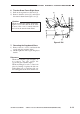
2. Removing the Editor Mirror
1) Remove the six face plates for screws.
2) Remove the two screws (M8x8), six
screws (M8x10), and six screws (M8x28),
a total of 14 screws; then, detach the
copyboard cover.
3) Remove the two screws, and detach the
controller PCB cover.
4) Remove the flat cable [1], and five screws
[2]; then, remove the controller PCB
support plate [3].
5) Remove the mirror plate [4].
Figure 9-719
[1]
[2]
[3]
[1]
[4]
[2][2]