
User Guide


CHAPTER 6 IMAGE FORMATION SYSTEM
6-68
COPYRIGHT
©
1999 CANON INC. CANON CLC1120/1130/1150 REV.0 MAR. 1999 PRINTED IN JAPAN (IMPRIME AU JAPON)
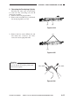
4) Peel off the double-sided adhesive tape
from under the gear cover sheet.
5) Remove the three screws [5], and detach
the developing assembly lower cover [6].
The screw identified as [5a] is tightened
over the white line.
Figure 6-637
6) Remove the resin screw [7] found at the
front of the developing assembly, and
detach the electrode plate cover [8].
Figure 6-638
7) Remove the two screws [9]; then, detach
the bias wire [10] and the electrode [11] of
the developing cylinder.
Figure 6-639
[5] [6] [5a]
[7][8]
[9][11] [10]