
User Guide


COPYRIGHT
©
1999 CANON INC. CANON CLC1120/1130/1150 REV.0 MAR. 1999 PRINTED IN JAPAN (IMPRIME AU JAPON)
6-17
CHAPTER 6 IMAGE FORMATION SYSTEM
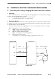
III. CONTROLLING THE CHARGING MECHANISM
A. Controlling the Primary Charging Mechanism and the Grid Bias
1. Operation
The mechanism used to control the primary charging/grid bias of the primary charging
assembly has the following items of control:
1. Controlling primary charging to a constant current.
2. Controlling the grid bias to a constant voltage.
2. Protection Circuit
The overcurrent detection circuit is used as a grid bias protection circuit. If overcurrent occurs,
for example, as a result of a short circuit on the grid plate, the circuit will be turned off for about 0.1
sec and then will be reset automatically.
If a short circuit continues on the grid plate for some reason, all images will be error images.
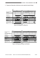
Each of the signals is used for the following:
[1] HVPR (primary current activation signal)
When ‘1’, high voltage is generated.
[2] HVGIC (grid bias activation signal)
When ‘1’, a grid bias is ready for application.
[3] HVGI (grid bias level signal)
Controlled to +8 to +16 V; high voltage is generated at +16 V or less.
Figure 6-301
J1012
-A11
-A10
-A9
J411
-3
-4
-5
T302
J413
[1]
[2]
[3]
HVPR
HVGIC
HVGI
DC driver PCB HVT-DC PCB
Primary charging
Grid bias
Photosensitive
drum