
User Guide


4.3 Logic Board Replacement
4.3.1 Except for EEPROM replacement
Various settings, waste ink level, number of sheets fed and other printer data are
stored to the EEPROM (IC501) on the logic board. When the board has been replaced
with a new one during servicing, operation using the same printer settings is possible
by removing the EEPROM from the logic board before it is replaced, and attaching it
to the new logic board. (refer to
Part 3: 3.6.1 Continued use of EEPROM memory data
(page 3-27)
. In this case, you need not replace the waste ink absorbers.)
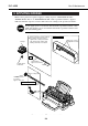
The EEPROM is attached onto the logic board by a socket, which makes replacement
relatively simple. When replacing the EEPROM, though, do not bend or deform the
EEPROM pins or subject the EEPROM to static electricity. We recommend wearing
wrist straps to discharge static electricity and using the ROM extractor to remove the
EEPROM.
After you have replaced the logic board, perform EEPROM list print (refer to
"Part 3:
3.4.2 Service mode" (page 3-24)
) to check the EEPROM data settings. (That is, check
that there is no major discrepancy between the waste ink level, waste ink optimizer
level, device IDs, information for detecting remaining ink level, number of sheets fed,
and other printing data compared with the actual state of the absorbers and
conditions of use.
4.3.2 EEPROM replacement
We recommend replacing the logic board if the printer is used frequently, or you
doubt the integrity of EEPROM data settings. However, in this case, you must replace
the waste ink absorbers (refer to
"Part 5: 4.4 Waste Ink Absorber" (page 5-10)
) and
initialize the EEPROM. For details, see
"Part 3: 3.4.2 Service mode" (page 3-24)
.
After that, perform EEPROM list print and confirm the contents of EEPROM data.
5-9
BJC-8500
Part 5: Maintenance
EEPROM
Figure 5-9 EEPROM