User’s Manual EZ-1000Plus P/N. 920-012411-03 Rev. A, 08.
FCC COMPLIANCE STATEMENT FOR AMERICAN USERS This equipment has been tested and found to comply with the limits for a CLASS A digital device, pursuant to Part 15 of the FCC Rules. These limits are designed to provide reasonable protection against harmful interference when the equipment is operated in a commercial environment.
Safety Instructions Bitte die Sicherheitshinweise sorgfältig lesen und für später aufheben. 1. Die Geräte nicht der Feuchtigkeit aussetzen. 2. Bevor Sie die Geräte ans Stromnetz anschließen, vergewissern Sie Sich, dass die Spannung des Geräts mit der Netzspannung übereinstimmt. 3. Nehmen Sie das Gerät bei Überspannungen (Gewitter) vom Netz. Das Gerät könnte sonst Schaden nehmen. 4. Sollte versehentlich Flüssigkeit in das Gerät gelangen, so ziehen sofort den Netzstecker.
Safety Instructions Please read the following instructions seriously. 1. Keep the equipment away from humidity. 2. Before you connect the equipment to the power outlet, please check the voltage of the power source. 3. Disconnect the equipment from the voltage of the power source to prevent possible transient over voltage damage. 4. Don’t pour any liquid to the equipment to avoid electrical shock. 5. ONLY qualified service personnel for safety reason should open equipment. 6.
1. BARCODE PRINTER................................................................... 5 1-1. Printer Accessories ......................................................................................................... 5 1-2. General Specifications .................................................................................................... 5 1-3. Communication Interface ................................................................................................ 7 1-4. Printer Parts .............
1. Barcode Printer 1-1. Printer Accessories After unpacking, please check the accessories that come with the package, and store appropriately. Barcode printer Power cord Switching Power USB Cable Label Ribbon Empty Ribbon Roll Quick Start Guide CD (includes label editing software QLabel / Manual) 1-2.
Barcodes Code Pages Graphics Interfaces Control Panel Power Environment Humidity Agency Approvals 1-D Bar codes: Code 39, Code 93, Code 128 (subset A, B, C), UCC/EAN-128 K-Mart, UCC/EAN-128, UPC A / E (add on 2 & 5), I 2 of 5, I 2 of 5 with Shipping Bearer Bars, EAN 8 / 13 (add on 2 & 5), Codabar, Post NET, EAN 128, DUN 14, HIBC, MSI (1 Mod 10), Random Weight, Telepen, FIM, China Postal Code, RPS 128 and GS1 DataBar 2-D Bar codes: PDF417, Datamatrix code, MaxiCode, QR code and Micro QR code CODEPAGE 437,
1-3. Communication Interface Parallel Interface Handshake Interface cable Pin out PIN NO.
Internal Interface UART1 wafer N.C TXD RXD CTS GND RTS E_MD RTS E_RST +5V GND +5V UART2 wafer +5V CTS TXD RTS RXD GND 1 2 3 4 5 6 7 8 9 10 11 12 1 2 3 4 5 6 EZ-1000Plus User’s Manual 1 2 3 4 5 6 7 8 9 10 11 12 Ethernet module N.
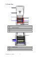
1-4. Printer Parts 1 2 3 5 4 6 7 8 1. 2. 3. 4. 5. 6. 7. 8. Cover Open Button Top Cover Label Roll Core Ribbon Rewind Wheel Print Mechanism Ribbon Rewind Shaft + Empty Ribbon Roll Locking Tenon (left/right) Front Cover Piece 4 1 2 3 5 1. 2. 3. 4. 5.
1 4 2 5 3 1. 2. 3. 4. 5. Ribbon Supply Shaft Label Guide Platen Roller Print Line Adjustment Gear Label Sensor 3 4 5 6 7 1 2 1. Fan-Fold Label Insert 2. Power Switch 3. Ethernet Socket (Option) 4. USB Port 5. Parallel Port 6. Serial Port (RS-232) 7. Power Socket * The communication ports may vary depending on product types.
2. Printer Installation This printer model has the following print modes: Thermal When printing, ribbon must be installed to transfer the print contents onto the Transfer (TT) media. Direct Thermal When printing, no ribbon is necessary; it only requires direct thermal media. (DT) Please check which print mode you will use and then go into the Setting Mode to change the print mode setting if necessary. 2-1. Ribbon Installation 1.
4. Feed the ribbon from the Ribbon Supply Shaft under the Print Head. 5. Wrap the ribbon around the Ribbon Shaft and stick the ribbon onto the Empty Ribbon Roll Core. 6. Firmly close the upper print mechanism.
2-2. Label Installation 1. Open the top cover by pressing the Cover Open Buttons on both sides. 2. Place the label roll onto the Label Roll Core. 3. Loosen and lift the upper print mechanism by pressing the locking tenons. 4. Feed the label through the two Label Guides to the Tear-off Bar. 5. Align the label guides to the label edge. 6. Close the upper print mechanism from the top to finish label installation.
2-3. Label Roll Core Installation Instruction (A) 1” roll core installation (B) 1.
2-4. Card / Hang tags Installation When installing cord tags, the tag hole must align with the sensor arrow (as indicated in figure), then use the Label Guide to secure the tags. Tag hole position Sensor Detection Position Sensor 2-5. PC Connection 1. 2. 3. 4. Please make sure the printer is powered off. Take the power cable, plug the cable switch to the power socket, and then connect the other end of the cable to the printer power socket.
2-6. Driver Installation 1. Insert product CD to your computer’s CD Drive and find the "Windows Drives" folder. 2. Select the icon of driver file and click it to start the installation. 3. Follow the instruction on screen to keep the installation going. Then the Driver Wizard utility should run automatically. 4. Select "Install printer drivers". 5. Select printer model.
6. Select connection port. 7. Enter the printer name and set printer sharing option. 8. A description page of printer settings will be displayed after all settings are completed. 9. Check if all printer settings are correct and then press Finish to start copying driver files. 10. Wait for file copying finished and complete the installation. 11. After the driver installation is complete, there should be a new printer model on Windows "Printer and Faxes" setting.
3. Accessory 3-1. Stripper Module Installation 1 Stripper Module 2 Screw (TAP 3*8) x 2pcs 【Note1】 Please power off the printer before installing the stripper module. 【Note2】 Label liner thickness is recommended to be 0.06mm ± 10% with basic weight 65g/㎡± 6%. 【Note3】The max width for stripper is 110mm 1. Open the top cover by pressing the Cover Open Buttons on both sides. 2. Loosen and then lift the upper print mechanism by pressing the locking tenons. 3.
5. Plug in the stripper connector onto the switchboard socket. (refer to the right figure) 【Note】 There are 2 sockets on the converting boards (one is for stripper installation, and another one is for cutter), before plug the connector into socket, please check the pin first. 6. Place the left side of the stripper first, and then fit the right side. 7. Hold the stripper module and tighten the screws. 8. Feed the label through the Label Guides.
10. Follow the direction as shown in figure to feed the liner across the stripper. 11. Close the upper print mechanism and the stripper. 12. Press the FEED key to adjust the position of label and complete the installation.
3-2. Cutter Module Installation 1 Cutter Module 2 Screw (TAP 3*8) x 2pcs 【Note1】 Please power off the printer before installing the cutter module. 【Note2】 Do not cut self-adhesive labels! The traces of adhesive will pollute the rotary knife and impair safe operation! The service life of the cutter is 500,000 cuts with 160g/㎡ paper weight and 250,000 cuts with 200g/㎡ paper weight. 1. Open the top cover by pressing the Cover Open Buttons on both sides. 2.
6. Place the left side of the stripper first, and then fit the right side. 7. Flip the cutter module downward to open the cutter. 8. Hold the cutter module and lock it with screws 9. After the screws are locked, flip close the cutter module. 10. Feed the label through the Label Guides. 11. Close the mechanism to complete the cutter module installation. 【Note】 It is not suggested to use label-inside paper when printing with cutter module. 12.
3-3. Ethernet Module Installation 1 2 3 4 5 6 Ethernet Cable 1.8M Bracket Ethernet module Module Connection Wire Bracket Screw*2 Secure Screw*1 1 2 4 【Note】 3 6 5 Please make sure that anti-static precautions are adopted during the installation. 1. Make sure the power is off and the power cable is unplugged. Place the printer onto a smooth surface and flip the whole printer unit upside down. 2. Unscrew the screws as indicated in figure. 3. Press the Cover Open Button and open the top cover.
7. Cut the cable tie on the Module Connection Wire. Then Plug the connector into the socket on Ethernet module. 【Note】 Please cut the cable tie carefully. Do not damage the Module Connection Wire. 8. Align the Ethernet module to the Ethernet port and plug into it. 9. Thread the Module Connection Wire through the other connection wires on the mainboard as the direction showed in figure.
3-4. WLAN Module Installation 1 2 3 4 5 6 7 8 9 10 11 1. Ethernet Cable 1.8M Secure Screw*1 Bracket Screw*2 Module Bracket WLAN module Module Connection Wire WLAN Antenna Nut (for Antenna) Washer (for Antenna) Fixture Plate Antenna Bracket Make sure the power is off and the power cable is unplugged. Place the printer onto a smooth surface and flip the whole printer unit upside down. 2. Unscrew the screws as indicated in figure. 3. Press the Cover Open Button and open the top cover. 1 2 4.
7. Cut the cable tie on the Module Connection Wire. Then Plug the connector into the socket on WLAN module. 【Note】 Please cut the cable tie carefully. Do not damage the Module Connection Wire. 8. Align the WLAN module to the Ethernet port and plug into it. 9. Secure the module onto the back plate. 10. Thread the Module Connection Wire through the other connection wires on the mainboard as the direction showed in figure. Then arrange the Antenna Connection Wire as the arrow showed.
13. Put the Fixture Plate first then the Washer and tighten the Nut to mount Antenna Connection Wire on the printer. 【Note】 It is suggested to tighten the Nut with long-nose pliers when mounting the Antenna Connection Wire. 14. Turn the Antenna according to the direction as arrow showed to mount it on the Antenna Connection Wire. The angle of Antenna can be adjusted if needed. 15.
3-5. CF Card Adapter Installation 1 2 CF Card Adapter (Front) CF Card Adapter (Back) 2 1 【Note】 Please power off the printer before installing the CF Card Adapter. 1. Open the top cover by pressing the Cover Open Buttons on both sides. 2. Take off the label roll core. 3. Open and remove the plastic cover from the inner base. 4. Check the correspondent pins and sockets to plug the adapter card onto the main board.
3-6. CF Card Instruction EZ-1000Plus series printers can read the CF Card after installed the CF Card Adapter. If the built-in memory is insufficient for storing label formats, graphics or fonts, users can use CF Card as external memory to provide more memory space. When using the CF card, please follow the instruction as below: 1. 2. 3. 4. 5. 6. Please power off the printer before installing or removing CF Card from the card slot.
4. Printer Setting 4-1. FEED Key After pressing the FEED key, printer will feed the media (according to media type) to the specified stop position. When printing with continuous media, pressing the FEED key will feed the media out to a certain length. When printing with labels, the printer will feed one label each time the FEED key is pressed. If the label is not sent out in a correct position, please proceed with the Auto Sensing (see next section). 4-2.
4-4. Self-Test page The Self-Test page helps user to figure out whether the printer is operating normally. Below are some general descriptions about the content of Self-Test page: Model & Version Serial port setup USB port setting EZXXXX : VX.XXX Serial port :96,N,8,1 int-usb sw setting: ext-USB Test pattern Number of DRAM installed Image buffer size Number of forms Number of graphics Number of fonts Number of Asian fonts Number of Databases Number of Scalable fonts Free memory size Speed, Density, Ref.
4-5. Error Messages LED Light Ready Status Red (Flash) Beep Description Red 4 beeps twice Print head is not firmly closed. Red (Flash) None Red 3 beeps twice Red 2 beeps twice Red 2 beeps twice Red 2 beeps twice Red 2 beeps twice Red 2 beeps twice EZ-1000Plus User’s Manual Solution Re-open the print head and make sure it closes tightly. Wait for the print head temperature drops to the The temperature of print head normal temperature range, is too high.
5. Maintenance and Adjustment 5-1. Thermal Print Head Cleaning Unclear printouts may be caused by dusty print head, ribbon stain or label liner glue. Therefore when printing, it’s necessary to keep the top cover closed. Also, check and prevent paper/label from being stained or dusty to ensure print quality and to prolong the print head life. Print head cleaning instructions are as follows: 1. 2. 3. 4. 5. Power-off the printer. Open the top cover. Take out the ribbon.
5-3. Print Line Adjustment To get better printing balance and quality, use print head adjusting gear to adjust the contacting surface between print head and label. 1. 2. A When turning print head adjusting gear counter-clockwise (as arrow 1 shows), print head would move in the direction where arrow A shows. 1 B When turning print head adjusting gear clockwise (as arrow 2 shows), print head would move in the direction where arrow B shows. 2 5-4. Adjust the cutter 1.
5-5.
Appendix Certifications EZ-1000Plus User’s Manual 36
EZ-1000Plus User’s Manual 37
EZ-1000Plus User’s Manual 38
EZ-1000Plus User’s Manual 39
EZ-1000Plus User’s Manual 40
EZ-1000Plus User’s Manual 41
EZ-1000Plus User’s Manual 42