
Installation / Operation Instruction Manual


37
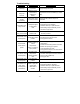
PARTS DIAGRAM
PART NAME AND DESCRIPTION
1. Blower
A
ssembl
y
12. Anode
–
Nipple
2. Temp. Switch 13. T&P Relief Valve Openin
g
3. Pressure Switch 14. Pilot Assembl
y
4. Flue Baffle 15. Main Burner Orifice
5. Hone
y
well Gas Control Valve 16. Gas Feedline
6. Drain Valve 17. Flammable Vapors Sensor
7. Fiber
g
lass Insulation
(
not shown
)
18. Sensor Harness
8. Foam Insulation
(
not shown
)
19. Blower Harness
9. Outer Door 20. Inner Door
A
ssembl
y
10. Steel Burner 21. Adapter
11. Diptube-Nipple 22. Vapor sensor bracke
t