
Installation Manual


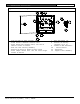


Table Of Contents
- Agencies
- About This Manual
- General Information
- Safety Symbols and Their Meanings
- Conflicts with Other Documents
- Table of Contents
- Figures
- Tables
- _
- 1.0 System Overview
- 1.1 System Components Description
- 1.2 Compatible Parts
- 1.3 System Components and Specifications
- 1.4 Transmitters
- 1.5 Cables
- 1.6 Batteries
- 1.7 Enclosures
- 1.8 Miscellaneous
- 2.0 Equipment Estimation
- 3.0 Installation Instructions
- 4.0 System Power-up and Debug
- 5.0 Testing and Troubleshooting
- _
- Appendix

Security Escort | Installation and Setup Guide |3.0
Installation Instructions
EN | 35
Bosch Security Systems | 1/09 | 33831E
Figure 15: Mounting the EA120 to the AE1 Enclosure
1
2
5
3
4
6
87
9
10
11
12
1 - Flip-up view to show retainer tabs.
2 - Slide board in-between retainer
tabs.
3 - Place board over support posts, use
two of smaller screws to secure.
4 - Hole for lock and key assembly.
5 - Outline of where to mount circuit
board.
6 - Place tamper switch here. Use the
three longer screws to secure.
7 - Wire entrances (6)
8 - Outline of battery location (1 or 2)
9 - Inside of AE1 Enclosure
10 - Circuit board
11 - Enclosure
12 - Support Post Assembly
Figure 16: Mounting the EA120 in the
AE101 Enclosure
1
2
3
4
5
1 - Use the two plastic screws here.
2 - Outline of where to mount circuit
board.
3 - Insert the stand-offs into these
holes, then stick to the inside of
the enclosure.
4 - Outline of where to place battery
(only 3 Ah battery fits.)
5 - Inside the AE101 Enclosure.
Wiring
The alert unit gets its main power
(for horn/strobe activation) from the
18 VAC transformer and its backup
power from a battery. However, the
multiplex bus continues to supply the
transponder information on status and
troubles in the event local power is
lost.
• Connect bus wires.
• Connect siren/strobe wires.
• Connect tamper wires, if used.
Set the Address
Every module on each multiplex bus of
the transponder must have its own
address. Set the address on the alert
unit using the address switch. See the
EA120 Installation Instructions.
Use only address numbers 0 through 7.
Do NOT use address numbers 8 and 9.