
Installation Manual


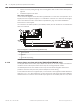


Table Of Contents
- Title Page
- Table of Contents
- Certifications, approvals, listings, and safety
- Introduction
- System overview
- Installation checklist
- Control panel installation
- Power supply
- Telephone communications
- IP communications
- Keypads, keyswitches, keyfobs and transmitters
- Keypads
- B915 Basic Keypad
- B920 Two-line Alphanumeric Keypad
- B921C Two-line Capacitive Keypad with Inputs
- B930 ATM Style Alphanumeric Keypad
- B942 Touch Screen Keypad
- Shortcuts and custom functions
- Address settings
- Supervision
- Installation and control panel wiring (keypads)
- Sensor loops overview and wiring (B921C/B942/B942W only)
- Output wiring (B942/B942W only)
- Troubleshooting
- Keyswitches
- RADION keyfobs and Inovonics pendant transmitters
- Keypads
- On-board outputs
- Off-board outputs
- On-board points
- Off-board points
- Wireless modules
- Access control
- Program and test the control panel
- Control panel board overview
- System wiring diagrams
- Approved applications
- Keypad Installer menu
- [1] Program menu
- [1] Reporting > [1] Phone menu parameters
- [1] Reporting > [2] Network menu parameters
- [1] Reporting > [3] Routing menu parameters
- [1] Reporting > [4] Personal Note menu parameters
- [2] Network > [1] Ethernet > (choose the bus module or on-board) > [1] Module Parameters menu
- [2] Network > [1] Ethernet > (choose the bus module or on-board) > [2] Address Parameters menu
- [2] Network > [1] Ethernet > (choose the bus module or on-board) > [3] DNS Parameters menu
- [2] Network > [2] Cellular > (choose the SDI2 cellular module or plug-in module)
- [3] RPS > [1] RPS Passcode menu parameters
- [3] RPS > [2] RPS Phone Number menu parameters
- [3] RPS > [3] RPS IP Address menu parameters
- [3] RPS > [4] RPS Port Number menu parameters
- [4] Area Options menu parameters
- [5] Keypad menu parameters
- [6] Users menu parameters
- [7] Points menu parameters
- [8] Disable Programming menu
- [2] Wireless menu
- [1] RF Point Menu> [1] Enroll Point RFID
- [1] RF Point Menu> [2] Replace Point RFID
- [1] RF Point Menu> [3] Remove Point RFID
- [2] RF Repeater Menu > [1] Add Repeater
- [2] RF Repeater Menu > [2] Replace Repeater
- [2] RF Repeater Menu > [3] Remove Repeater
- [3] RF Diagnostic Menu > [1] RF Points
- [3] RF Diagnostic Menu > [2] RF Repeater Menu
- [3] Diags menu
- [4] Serv Byp (Service Bypass) menu
- [5] Versions menu
- [6] Cloud menu
- [1] Program menu
- Specifications
- Appendix
- Back Page

4. Pull the necessary wiring through the mounting plate. Refer to Wire to the control panel,
page 56.
5. Install the keypad on the base.
Wire to the control panel
Connect B Series keypads to the SDI2 bus by parallel wire run from the control panel to each
keypad, wire from keypad to keypad, or a combination of the two. For maximum wire lengths,
refer to the SDI2 Bus section of the table in Specifications, page 147 and the installation
instructions for each keypad.
Use a maximum of 7500 ft (2286 m) of 22 AWG (0.8 mm) wire for all devices connected to the
SDI2 bus combined.
1
2
3
R
Y
G
B
7 COM 8
C
OUTPUT
B
1 k End of Line Resistors
Voltage Ranges
ON-BOARD POINTS
3.7 - 5.0 VDC
2.0 - 3.0 VDC
0.0 - 1.3 VDC
Open
Normal
Short
3 COM 4 5 COM 61 COM 2
R Y G B
SDI2
Device Bus
AUX
- 12 V +
TMPR
1 COM 2 7 COM 83 COM 4 5 COM 6
RESET
COM AUX
R Y G B
PWR A B COM
B C
OUTPUT
Figure 9.1: Keypad to control panel wiring (B5512 shown)
1
Control panel
2 Keypad
3 Terminal strip wiring
Sensor loops overview and wiring (B921C/B942/B942W only)
The keypad detects three states (Open, Supervised, Short) on its sensor loops and sends the
conditions to the control panel. Each sensor loop has an assigned point number.
Use twisted-pair wire for the module sensor loops to avoid electromagnetic interference
problems. Run wires away from the premises telephone and AC wiring.
To wire detection devices to keypad inputs, connect them to the keypad terminals labeled for
COM, and 1, 2, 3, or 4. Wire resistance on each sensor loop must be less than 100 Ω with the
detection devices connected. The terminal strip supports 12 to 22 AWG (0.65 to 2 mm) wires.
9.1.10
56 en | Keypads, keyswitches, keyfobs and transmitters Control Panel
2016.05 | 14 | F.01U.287.180 Installation and System Reference Guide Bosch Security Systems, Inc.