
Installation Manual


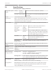


Table Of Contents
- Title Page
- Table of Contents
- Certifications, approvals, listings, and safety
- Introduction
- System overview
- Installation checklist
- Control panel installation
- Power supply
- Telephone communications
- IP communications
- Keypads, keyswitches, keyfobs and transmitters
- Keypads
- B915 Basic Keypad
- B920 Two-line Alphanumeric Keypad
- B921C Two-line Capacitive Keypad with Inputs
- B930 ATM Style Alphanumeric Keypad
- B942 Touch Screen Keypad
- Shortcuts and custom functions
- Address settings
- Supervision
- Installation and control panel wiring (keypads)
- Sensor loops overview and wiring (B921C/B942/B942W only)
- Output wiring (B942/B942W only)
- Troubleshooting
- Keyswitches
- RADION keyfobs and Inovonics pendant transmitters
- Keypads
- On-board outputs
- Off-board outputs
- On-board points
- Off-board points
- Wireless modules
- Access control
- Program and test the control panel
- Control panel board overview
- System wiring diagrams
- Approved applications
- Keypad Installer menu
- [1] Program menu
- [1] Reporting > [1] Phone menu parameters
- [1] Reporting > [2] Network menu parameters
- [1] Reporting > [3] Routing menu parameters
- [1] Reporting > [4] Personal Note menu parameters
- [2] Network > [1] Ethernet > (choose the bus module or on-board) > [1] Module Parameters menu
- [2] Network > [1] Ethernet > (choose the bus module or on-board) > [2] Address Parameters menu
- [2] Network > [1] Ethernet > (choose the bus module or on-board) > [3] DNS Parameters menu
- [2] Network > [2] Cellular > (choose the SDI2 cellular module or plug-in module)
- [3] RPS > [1] RPS Passcode menu parameters
- [3] RPS > [2] RPS Phone Number menu parameters
- [3] RPS > [3] RPS IP Address menu parameters
- [3] RPS > [4] RPS Port Number menu parameters
- [4] Area Options menu parameters
- [5] Keypad menu parameters
- [6] Users menu parameters
- [7] Points menu parameters
- [8] Disable Programming menu
- [2] Wireless menu
- [1] RF Point Menu> [1] Enroll Point RFID
- [1] RF Point Menu> [2] Replace Point RFID
- [1] RF Point Menu> [3] Remove Point RFID
- [2] RF Repeater Menu > [1] Add Repeater
- [2] RF Repeater Menu > [2] Replace Repeater
- [2] RF Repeater Menu > [3] Remove Repeater
- [3] RF Diagnostic Menu > [1] RF Points
- [3] RF Diagnostic Menu > [2] RF Repeater Menu
- [3] Diags menu
- [4] Serv Byp (Service Bypass) menu
- [5] Versions menu
- [6] Cloud menu
- [1] Program menu
- Specifications
- Appendix
- Back Page

Wire requirements
Terminal label Terminal description Requirements
18VAC AC 18 AWG min (up to 12 AWG max)
Earth ground 16 AWG min (up to 14 AWG max)
BAT + Battery + Bosch supplied wire lead, included with control
panel.
BAT - Battery -
OUTPUT A NO Output A normally open 22 AWG min (up to 12 AWG max)
OUTPUT A C Output A common
OUTPUT A NC Output A normally closed
COM Common
AUX + AUX power
PWR/R SDI2 power
A/Y SDI2 data bus A
B/G SDI2 data bus B
COM/B SDI2 common
1 Point 1
COM Point 1/2 common
2 Point 2
3 Point 3
COM Point 3/4 common
4 Point 4
5 Point 5
COM Point 5/6 common
6 Point 6
7 Point 7
COM Point 7/8 common
8 Point 8
OUTPUT B Output B
OUTPUT C Output C
21.1
Control Panel Specifications | en 149
Bosch Security Systems, Inc. Installation and System Reference Guide 2016.05 | 14 | F.01U.287.180