
Installation Manual


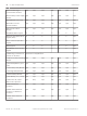
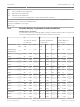

Table Of Contents
- Title Page
- Table of Contents
- Certifications, approvals, listings, and safety
- Introduction
- System overview
- Installation checklist
- Control panel installation
- Power supply
- Telephone communications
- IP communications
- Keypads, keyswitches, keyfobs and transmitters
- Keypads
- B915 Basic Keypad
- B920 Two-line Alphanumeric Keypad
- B921C Two-line Capacitive Keypad with Inputs
- B930 ATM Style Alphanumeric Keypad
- B942 Touch Screen Keypad
- Shortcuts and custom functions
- Address settings
- Supervision
- Installation and control panel wiring (keypads)
- Sensor loops overview and wiring (B921C/B942/B942W only)
- Output wiring (B942/B942W only)
- Troubleshooting
- Keyswitches
- RADION keyfobs and Inovonics pendant transmitters
- Keypads
- On-board outputs
- Off-board outputs
- On-board points
- Off-board points
- Wireless modules
- Access control
- Program and test the control panel
- Control panel board overview
- System wiring diagrams
- Approved applications
- Keypad Installer menu
- [1] Program menu
- [1] Reporting > [1] Phone menu parameters
- [1] Reporting > [2] Network menu parameters
- [1] Reporting > [3] Routing menu parameters
- [1] Reporting > [4] Personal Note menu parameters
- [2] Network > [1] Ethernet > (choose the bus module or on-board) > [1] Module Parameters menu
- [2] Network > [1] Ethernet > (choose the bus module or on-board) > [2] Address Parameters menu
- [2] Network > [1] Ethernet > (choose the bus module or on-board) > [3] DNS Parameters menu
- [2] Network > [2] Cellular > (choose the SDI2 cellular module or plug-in module)
- [3] RPS > [1] RPS Passcode menu parameters
- [3] RPS > [2] RPS Phone Number menu parameters
- [3] RPS > [3] RPS IP Address menu parameters
- [3] RPS > [4] RPS Port Number menu parameters
- [4] Area Options menu parameters
- [5] Keypad menu parameters
- [6] Users menu parameters
- [7] Points menu parameters
- [8] Disable Programming menu
- [2] Wireless menu
- [1] RF Point Menu> [1] Enroll Point RFID
- [1] RF Point Menu> [2] Replace Point RFID
- [1] RF Point Menu> [3] Remove Point RFID
- [2] RF Repeater Menu > [1] Add Repeater
- [2] RF Repeater Menu > [2] Replace Repeater
- [2] RF Repeater Menu > [3] Remove Repeater
- [3] RF Diagnostic Menu > [1] RF Points
- [3] RF Diagnostic Menu > [2] RF Repeater Menu
- [3] Diags menu
- [4] Serv Byp (Service Bypass) menu
- [5] Versions menu
- [6] Cloud menu
- [1] Program menu
- Specifications
- Appendix
- Back Page

B930 ______ 35 x Qty = ______ 35 x Qty = ______ 80 x Qty = ______
B942/B942W
3
______ 200 x Qty = ______ 200 x Qty = ______ 300 x Qty = ______
D125B ______ 25 x Qty = ______ 25 x Qty = ______ 168 x Qty = ______
D127 ______ 5 x Qty = ______ 5 x Qty = ______ 55 x Qty = ______
D129 ______ 23 x Qty = ______ 23 x Qty = ______ 25 x Qty = ______
D132A ______ 10 x Qty = ______ 10 x Qty = ______ 70 x Qty = ______
D133
4
______ x Qty = ______ x Qty = ______ x Qty = ______
D134
5
______ x Qty = ______ x Qty = ______ x Qty = ______
D185 ______ 245 x Qty = ______ 245 x Qty = ______ 300 x Qty = ______
D192G ______ 35 x Qty = ______ 35 x Qty = ______ 100 x Qty = ______
Ratings of other devices in the system that are not shown above:
____ ______ _____ x Qty = ______ ______ x Qty = ______ ____ x Qty = ______
____ ______ _____ x Qty = ______ ______ x Qty = ______ ____ x Qty = ______
____ ______ _____ x Qty = ______ ______ x Qty = ______ ____ x Qty = ______
____ ______ _____ x Qty = ______ ______ x Qty = ______ ____ x Qty = ______
Total A = ______ Total B = ______ Total C = ______
1
The In Alarm calculation for the B308 is: 20 x Qty + (16.25 x number of relays).
2
Currents listed are for the B450 only. Include plug-in device currents in calculations.
3
If using the proximity reader, add 100 mA to columns A, B, and C before calculating.
4
38 mA for each active relay.
5
Value = Minutes of alarm operation/60.
6
Use 110 mA + reader. Do not exceed 260 mA.
Table 19.1: Current rating chart for standby battery calculations
Total B
1
Hours Total C
1
Alarm Operation
2
Contingency Total Ah
3
( ________ x 24 ) + ( ________ x 0.083) + 15% = _________
1
Refer to previous table.
2
Value = Minutes of alarm operation/60
3
Total Ah requirements must not exceed the Ah capacity of batteries:
– One D126 Battery = 7 Ah
– Two D126 Batteries = 14 Ah
– One D1218 Battery = 18 Ah
Table 19.2: General ampere-hour (Ah) calculation formula
Application Minimum Required
Standby Time (hr)
Minimum Alarm Time (min)
Residential Burglary 4 4
Proprietary Burglary 4 N/A
Central Station (Bank) 72 N/A
100 en | Approved applications Control Panel
2016.05 | 14 | F.01U.287.180 Installation and System Reference Guide Bosch Security Systems, Inc.