
Installation Instructions


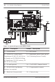


Table Of Contents

2-wire smoke wiring (D125B)
CCD 0x
-
0xxxx -
000
© RADIONICS INC.
D125B
1992
1
SWITCH
POWER
10
EARTH
GND
2
ZONE
B
4 5
PANEL
COMMON
3
ZONE
A
6
B-
LOOP
7
A-
LOOP
8
B+
LOOP
9
A+
LOOP
R21
R9
R10
R14
R11
R12
R22
RV2
RV3
RV4
R8
RV1
TB1/J1
R3
C1
R7
C3
C2
R13
R4
R5
R6
U1
PTC2
PTC1
R1
R2
D125B
1
2
3
4, 5
7, 9
6, 8
or
5
UX PWR
11
10
10
Figure 7.4: D125B to control panel wiring (B5512 shown)
Callout ᅳ Description Callout ᅳ Description
1 ᅳ Switched auxiliary power from
the control panel’s Output A (NC)
1
7 ᅳ Supervised smoke detector
to A LOOP negative
2 ᅳConnection from an on-board
point on the control panel to Zone B
8 ᅳ Supervised smoke detector
to B LOOP positive
3 ᅳ Connection from an on-board
point on the control panel to Zone A
9 ᅳ Supervised smoke detector
to A LOOP positive
4/5 ᅳ Connection to the control
panel’s common (one connection
only)
10 ᅳ Earth ground
6 ᅳ Supervised smoke detector to B
LOOP negative
11 ᅳ Output A jumper (under
cover) set to AUX PWR
1
You can also use Output B or C in conjunction with a D133 or D134 relay
module.
7.4
Control Panels System wiring diagrams | en 37
Bosch Security Systems, Inc. 2015.09 | 08 | F.01U.287.185