
User's Manual


44
1.2 How to connect the Antennae
Connect the antennae to the TNC sockets and ( . Set them at an angle (60°).
Please note that for diversity operation both antennae have to be connected. A weighting
circuit silently switches the signal with the better S/N ratio to the output.
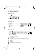
1.4 LC-Display and Menu Settings
On the LC-Display all operating parameters such as RF and AF level will be shown.
Using the “Menu“ control you can select from 6 options. The selected function is
surrounded by a square frame and shown at the bottom of the LC-Display.
By selecting the ESC button you can cancel the current entry into the menu to display the
previous setting.
To select the individual receiving channels of the NE 900 D / Q for entering the menu
settings, press the menu control until the green LED between the ACT and the SCAN
button is flashing. Turn the menu control to select the receiving channel. The green LED of
the selected receiving channel will flash. Press the menu control to confirm. The green LED
will illuminate permanently.
The functions and operation are described in the following.
1.3 Setting up
1. Place the diversity receiver in the same room or area as the transmitters. Make sure the
diversity receiver is placed as close as possible to the transmitter.
2. Ensure that the receiver is installed as close as possible to the mixing console or amplifier
so that the display can be seen at all times.
3. Do not place the diversity receiver near digitally controlled equipment.
4. Connect the AF-output to the corresponding input of the mixing console or amplifier.
5. Connect the receiver to AC power.
6. Switch on the receiver . The red LED will illuminate.
7. If you use the receiver on a tabletop, please stick the supplied rubber pads to the
bottom of the receiver to ensure a sufficient ventilation.
8. If you install the receiver into a 19" rack, please leave above and below a free space of
1 U to ensure a sufficient ventilation.
1310
1
1.4.1 Diversity indication of the Receiving Channel
Each receiving module has two separate receiving circuits, one for each antenna.
The signal with the better S/N ratio is switched to the output. The received diversity channel
is shown in the LC-display.
7
7
8
Opus900_BA_DEF_neu:Opus900_BA_DEF 26.09.2006 14:47 Uhr Seite 44