Model WPP9 ENGLISH........................................3 FRANÇAIS...................................25 ESPAÑOL.....................................49 In USA - BEST Hartford, Wisconsin In CANADA - BEST Drummondville, QC, Canada REGISTER YOUR PRODUCT ONLINE AT : www.BestRangeHoods.com/register For additional Information visit www.BestRangeHoods.
READ AND SAVE THESE INSTRUCTIONS ! INTENDED FOR DOMESTIC COOKING ONLY ! WARNING TO REDUCE THE RISK OF FIRE, ELECTRIC SHOCK, OR INJURY TO PERSONS, OBSERVE THE FOLLOWING: 1. Use this unit only in the manner intended by the manufacturer. If you have questions, contact the manufacturer at the address or telephone number listed in the warranty. 2. Before servicing or cleaning unit, switch power off at service panel and lock service panel to prevent power from being switched on accidentally.
WARNING TO REDUCE THE RISK OF INJURY TO PERSONS IN THE EVENT OF A RANGE TOP GREASE FIRE, OBSERVE THE FOLLOWING:* 1. SMOTHER FLAMES with a close-fitting lid, cookie sheet, or metal tray, then turn off the burner. BE CAREFUL TO PREVENT BURNS. If the flames do not go out immediately, EVACUATE AND CALL THE FIRE DEPARTMENT. 2. NEVER PICK UP A FLAMING PAN - You may be burned. 3. DO NOT USE WATER, including wet dishcloths or towels - violent steam explosion will result. 4. Use an extinguisher ONLY if: A.
CLEANING AND MAINTENANCE Proper maintenance of the Range Hood will assure proper performance of the unit. Motor The motor is permanently lubricated and never needs oiling. If the motor bearings make excessive or unusual noise, replace the motor with the exact service motor. The impeller should also be replaced. Grease Filter The grease filters should be cleaned frequently. Use a warm detergent solution. Grease filter are dishwasher safe.
OPERATION Controls (Fig.1) A B C D R Button A = turns the lights on/low/high/off. Button B = Activates/Deactivates the delay-off feature. Press once (when blower is on) to activate the delay-off feature. The selected speed level that is displayed in display “C” will blink when this feature is activated. After 10 minutes, the blower will then turn off. Delay can be deactivated at any time by pressing the button again. Display C = Indicates the selected speed of the blower 1, 2, 3, or b for boost.
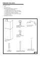
PREPARE THE HOOD Unpack hood and check contents.
EXTERIOR AND IN-LINE BLOWER SELECTION WPP9E Series CAUTION: To reduce risk of fire and electric shock, install this range hood only with Best Exterior Blower Models EB6, EB9, EB12 or EB15, and Best In-Line Blower Models ILB3, ILB6, ILB9 or ILB11. Other blowers cannot be substituited. The blower must be UL listed for Canadian and U.S. use, and evaluated for use with solid state speed control, rated 120V, 60 Hz, 6.0 A max.
IN-LINE BLOWER FIG. 5 INSTALL THE DUCTWORK (WPP9IQ and WPP9IQT) ROOF CAP 8” OR 10” ROUND DUCT NOTE: To reduce the risk of fire, use only metal ductwork. 1. Decide where the ductwork will run between the hood and the outside. 2. A straight, short duct run will allow the hood to perform most efficiently. It is recommended that there be a minimum of 6” of straight duct from to an elbow for 8” duct and 12” for 10” duct. 3. Long duct runs, elbows, and transitions will reduce the performance of the hood.
INSTALL THE HOOD Remove the plastic protective film from all exterior surfaces, decorative flues and filters, prior to final installation 1. Construct wood wall framing that is flush with interior surface of wall studs (Fig.7). Make sure: a) the framing is centered over installation location. b) the height of the framing will allow the hood to be secured to the framing within the dimensions shown. 2. Install the (2) 6 x 60mm screws for the top of the hood at the dimensions shown in Fig.8-9.
MOUNTING LAG SCREWS (6x60mm) WALL FRAMING G G LA NTIN 60mm) MOU x (6 S W SCRE FIG. 8 FIG.
WIRING (WPP9IQ and WPP9IQT) WIRING BOX COVER Note: This range hood must be properly grounded. The unit should be installed by a qualified electrician in accordance with all applicable national and local electrical codes. 1. Remove the wiring box cover. Remove a knockout from the wiring box (Fig.10). 2. Secure the conduit to the wiring box through a conduit connector. 3. Make electrical connections. Connect white to white, black to black and green to green. 4. Replace wiring box cover and screws.
INSTALL FLUE MOUNTING BRACKET DUCTED AND NON-DUCTED 1. Assemble the flue mounting bracket, adjusting outside width as shown. (Fig.12) 2. Carefully center the mounting bracket directly over the range hood location. 3. Secure the bracket assembly to the ceiling using (2) 4.8 x 38mm mounting screws and drywall anchors (Fig.13). Make sure the bracket is pushed into the corner, tight against the wall if necessary, and centered over the hood. Complete the installation.
NON-DUCTED INSTALLATION AVAILABLE ONLY FOR SINGLE BLOWER VERSION (WPP9IQ only) Note: a. Purchase Model ANKWPP9 Non-ducted Recirculation Kit from your local dealer. b. Rooms with 10 or 11 foot ceilings require Flue Extension Model AEWPP9SBN, available from your local dealer. Discard the upper flue supplied with the range hood and replace it with the longer flue extension. 1. Attach the 6”-to-8” adapter to blower discharge and tape joint with aluminum duct tape (Fig.16). 2.
INSTALL FILTERS DUCTED AND NON-DUCTED HOODS 1. To remove the GREASE filter, (Fig.19) push the filter towards the front so that it clears the filter channel, then pull down on the handle to disengage the filter from the hood. Tilt the filter downward and remove. 2. The grease filters and the drip tray (see page 5 for removal & cleaning instructions) should be cleaned frequently. Use a warm detergent solution. Grease filters and the oil collectors are dishwasher safe. 3.
CALIBRATE IQ BLOWER SYSTEMTM Ducted Internal Blower Hoods Only After the hood is installed and wired, engage the calibration process (our Guaranteed Performance System Technology) to ensure full-rated airflow is being delivered. Prior to calibration, ensure that all filters, light bulbs and duct system components are installed and sealed. CALIBRATION PROCESS Hold the calibration button for 3 seconds; calibration button will light up and stay on for up to 13 minutes.
WPP9 Programming Mode Procedure WPP9E Programming Mode Procedure The range hood is designed to work with several different blowers models. Before using the hood, the control must first be programmed to your blower model, in order to achieve proper operating speed: 1. Find the SETUP number that corresponds to the blower model that is installed with your range hood. 2. There must be power to the hood but the blower and lights must be turned off. 3.
SERVICE PARTS MODEL WPP9IQ KEY NO. PART NO.
- 19 -
SERVICE PARTS MODEL WPP9IQT KEY NO. 9 17 17 17 17 37 67 67 114 115 116 130 130 130 130 195 202 274 415 439 474 485 506 507 * AQI ARU IME CAS PART NO.
- 21 -
SERVICE PARTS MODEL WPP9E KEY NO. 9 17 17 17 17 37 67 67 114 115 116 130 130 130 130 195 202 274 415 474 485 * AQI ARU IME PART NO.
- 23 -
- 24 -
Modèle WPP9 ENGLISH........................................3 FRANÇAIS...................................25 ESPAÑOL.....................................49 Aux États-Unis - BEST Hartford, Wisconsin Au CANADA - BEST Drummondville, QC, Canada ENREGISTREZ VOTRE PRODUIT EN LIGNE À : www.BestRangeHoods.com/register Pour de plus amples informations, visitez www.BestRangeHoods.
- 26 -
LIRE CES DIRECTIVES ET LES CONSERVER ! CONÇUE POUR LES CUISINES PRIVÉES UNIQUEMENT ! AVERTISSEMENTS POUR RÉDUIRE LES RISQUES D’INCENDIE, D’ÉLECTROCUTION OU DE BLESSURES PHYSIQUES, RESPECTEZ LES INSTRUCTIONS CI-DESSOU: 1. Utilisez cet appareil uniquement de la manière prévue par le fabricant. Si vous avez des questions, contactez le fabricant à l’adresse ou au numéro de téléphone indiqués dans la garantie. 2.
AVERTISSEMENTS POUR RÉDUIRE LE RISQUE DE BLESSURES PHYSIQUES EN CAS DE FEU DE FRITURE SUR LA TABLE DE CUISSON, VEUILLEZ PROCÉDER COMME SUIT :* 1. ÉTOUFFEZ LES FLAMMES avec un couvercle hermétique, une plaque à biscuits ou un plateau en métal, puis éteignez le brûleur. SOYEZ PRUDENT(E) AFIN D’ÉVITER LES BRÛLURES. Si les flammes ne s’éteignent pas immédiatement, ÉVACUEZ LE LIEU ET APPELEZ LE SERVICE DES POMPIERS. 2. NE SAISISSEZ JAMAIS UNE POÊLE ENFLAMMÉE, vous risquez de vous brûler. 3.
NETTOYAGE ET ENTRETIEN Pour assurer les performances de l'appareil, entretenez-le de manière appropriée. Moteur Le moteur est lubrifié en permanence et aucun graissage n'est nécessaire. Si les roulements du moteur font un bruit excessif ou inhabituel, remplacez le moteur par une pièce de rechange identique. Remplacez aussi les hélices. Filtre à graisse Le filtre à graisse doit être nettoyé souvent. Vous pouvez utiliser une solution détergente chaude ou le mettre dans le lave-vaisselle.
FONCTIONNEMENT COMMANDES (Fig.1) A B C D R Bouton A = tourne les lumières / basse / haute / arrêt. Bouton B = active / désactive la fonction retard-off. Appuyez une fois (lorsque la soufflerie est activée) pour activer la fonction retard-off. Le niveau de vitesse sélectionnée qui est affichée dans l’affichage “C” clignote lorsque cette fonction est activée. Après 10 minutes, le ventilateur s’éteindra. Le retard peut être désactivé à tout moment en appuyant sur le bouton.
PRÉPARATION DE LA HOTTE Déballez la hotte et vérifiez le contenu de l’emballage.
CHOIX DE VENTILATEUR EXTERNE OU “IN-LINE” WPP9E Series ATTENTION: Pour réduire les risques d’incendie et électrique, installer cette hotte seulement avec un ventilateur extérieur Best Modèles EB6, EB9, EB12 ou EB15, et les ventilateur en ligne Best Modèles ILB3, ILB6, ILB9 ou ILB11 uniquement. On ne peut pas utiliser d’autres ventilateurs (les ventilateurs sont vendus séparément).
VENTILATEUR IN-LINE FIG. 5 INSTALLER LES CONDUITS (WPP9IQ et WPP9IQT) CAPUCHON DU TOIT CONDUIT ROND DE 8” À 10” REMARQUE: pour réduire les risques d’incendie, utilisez uniquement des conduits métalliques. 1. Décidez où le tuyau doit être installé, entre votre hotte et l’extérieur. 2. Un conduit droit et court permettra à votre hotte de fonctionner d’une façon plus efficace. Il est recommandé qu’il y ait un minimum de 6” de conduit droit à un coude pour 8” conduit et 12” pour 10” conduit. 3.
INSTALLEZ LA HOTTE Remarque : avant l'installation finale, retirez STRUCTURE DERRIÈRE LE la pellicule en plastique de toutes les surfaces SUPPORT EN BOIS CROISÉ extérieures, des carneaux décoratifs et des filtres. 1. Construisez une structure murale en bois à niveau avec la surface intérieure des poteaux de cloison (Fig.7). Assurez-vous: a) que la structure est centrée sur l'emplacement d'installation.
VIS D’ASSEMBLAGE (6x60mm) PLANCHE DE BOIS POUR L'ADAPTATION AGE EMBL ’ASS VIS D x60mm) (6 FIG. 8 FIG.
INSTALLATION ELECTRIQUE (WPP9IQ et WPP9IQT) COUVERCLE DE LA BOÎTE DE CONNEXION Remarque: Ce modèle de hotte doit être relié à la terre correctement. Cet article devrait être installé par un électricien qualifié selon les lois nationales et locales en matière d’électricité. 1. Enlevez le couvercle de la boîte de connexion électrique. Ouvrez un trou de la boîte de connexion électrique (Fig.10). 2. Fixer le “conduit” au boîtier de connexion à l’aide d’un connecteur approprié pour ce “conduit”. 3.
INSTALLATION DU SUPPORT DE MONTAGE DU CARNEAU HOTTES CANALISÉES ET NON CANALISÉES 1. Montez le support de montage du carneau en réglant la largeur extérieur comme indiqué. (Fig.12) 2. Centrez avec soin le support de montage directement au-dessus de l'emplacement de la hotte de cuisine. 3. Fixez l'ensemble du support au plafond à l'aide de 2 vis de montage de 4,8 x 38 mm et des ancrages pour cloison sèche (Fig.13).
INSTALLATION HOTTE NON CANALISÉE UNIQUEMENT DISPONIBLE POUR LE SINGLE VERSION (WPP9IQ seulement) Remarque: a. Achat Modèle ANKWPP9 Kit de recirculationnon canalisé auprès de votre revendeur local. b. Chambres avec plafond de 10 ou 11 pieds, exigentle kit d’extension modèle AEWPP9SBN, disponibles auprès de votre revendeur local.Jeter le carneau supérieure fournie avec lahotte et le remplacer par l’extension plus. 1.
INSTALLATION DES FILTRESS HOTTES CANALISÉE ET NON CANALISÉE 1. Pour retirer le filtre à GRAISSE, (Fig.19) pousser le filtre vers l’avant pour qu’il efface le canal du filtre, puis tirez sur la poignée pour dégager le filtre de la hotte. Inclinez le filtre vers le bas et la retirer. 2. Les filtres à graisse et la gouttière (voir page 5 pour les instructions de démontage et nettoyage) doivent être nettoyés fréquemment. Utilisez une solution de détergent chaude.
CALIBRER LE VENTILATEUR QIMC Seulement canalisés Hotte ventilateur interne Après l’installation de la hotte encastrable, enclencher le processus de calibrage (notre Technologie de performance garantie s’assure que le débit d’air optimal soit emis). Avant d’entreprendre le processus de calibrage, s’assurer que les filtres, les ampoules et le conduit soient installés.
WPP9 Mode de Programmation Procédure Mode de Programmation WPP9E Procédure La hotte est conçu pour fonctionner avec différents modèles de souffleuses. Avant d’utiliser la hotte, le contrôle doit d’abord être programmé pour votre modèle soufflerie, afin d’atteindre une vitesse de fonctionnement correct: 1. Trouvez le numéro de configuration qui correspond au modèle du ventilateur qui est installé avec votre hotte. 2. Il faut pouvoir le capot mais le ventilateur et les lumières doivent être éteintes. 3.
PIÈCES DE RECHANGE MODÈLE WPP9IQ N. PART NO.
- 43 -
PIÈCES DE RECHANGE MODÈLE WPP9IQT N. PART NO.
- 45 -
PIÈCES DE RECHANGE MODÈLE WPP9E N. PART NO.
- 47 -
- 48 -
Modelo WPP9 ENGLISH........................................3 FRANÇAIS...................................25 ESPAÑOL.....................................49 En EE.UU.: BEST Hartford, Wisconsin En CANADÁ - BEST Drummondville, QC, Canada REGISTRE SU PRODUCTO EN LÍNEA EN: www.BestRangeHoods.com/register Para obtener información adicional visite www.BestRangeHoods.
- 50 -
LEA Y CONSERVE ESTAS INSTRUCCIONES ! PARA COCINAS DOMÉSTICAS SOLAMENTE ! ADVERTENCIA PARA REDUCIR EL RIESGO DE INCENDIOS, DESCARGAS ELÉCTRICAS O LESIONES PERSONALES, RESPETE LO SIGUIENTE: 1. Utilice esta unidad sólo de la manera prevista por el fabricante. Si tiene preguntas, comuníquese con el fabricante a la dirección o el número de teléfono que aparecen en la garantía. 2.
ADVERTENCIA PARA REDUCIR EL RIESGO DE LESIONES PERSONALES EN CASO DE UN INCENDIO POR GRASA EN LA COCINA, RESPETE LO SIGUIENTE: * 1. SOFOQUE LAS LLAMAS con una tapa bien ajustada, una bandeja para hornear o una bandeja metálica y luego apague el quemador. TENGA LA PRECAUCIÓN DE EVITAR QUEMADURAS. Si las llamas no se apagan inmediatamente, SALGA Y LLAME A LOS BOMBEROS 2. NUNCA TOQUE UNA CACEROLA EN LLAMAS: puede quemarse. 3. NO USE AGUA, incluso toallas o repasadores húmedos.
LIMPIEZA Y MANTENIMIENTO El mantenimiento adecuado de la campana para cocina garantizará el rendimiento correcto de la unidad. Motor El motor está constantemente lubricado y nunca necesita engrase. Si los cojinetes del motor hacen un ruido excesivo o inusual, reemplace el motor con el mismo motor de servicio. También se debe reemplazar el propulsor. Filtro de grasas Se debe limpiar el filtro de grasas regularmente. Utilice una solución de detergente tibia. El filtro de grasas es apto para lavavajillas.
FUNCIONAMIENTO Controles (Fig.1) A B C D R Botón A = Enciende las luces encendido/bajo/alto/apagado Botón B = Activa/Desactiva la función de apagado por retardo. Presione una vez (cuando el extractor este encendido) para activar la función de apagado por retardo. El nivel de velocidad que es desplegado en la pantalla “C” parpadeará cuando este activada esta función. Después de 10 minutos, el extractor se apagara. La función de retardo puede ser desactivada presionando el botón en cualquier momento.
PREPARACIÓN DE LA CAMPANA Desensamble la campana y revise el contenido. Debe recibir: 1 - Campana 1 - Conjunto de conducto de chimenea decorativa 1 - Bolsa de piezas (B080810995) que contiene: 1 - Soporte de montaje 2 - Tornillos de montaje (Cabeza plana 3.9 x 6 mm) 2 - Tornillos de montaje (Cabeza troncocónica 3.9 x 9.5 mm) 4 - Tornillos de montaje tirafondos (6 x 60mm) 2 - Tornillos de montaje (Cabeza troncocónica 4.
SELECCIÓN DEL VENTILADOR EXTERIOR O DEL VENTILADOR IN-LINE WPP9E Series PRECAUCIÓN: Para reducir el riesgo de incendios y descargas eléctricas, instale esta campana sólo con el ventilador exterior Best Modelos EB6, EB9, EB12 o EB15 y Best InLine ventilador Modelos ILB3, ILB6, ILB9 o ILB11. Otros ventiladores no puede substituirse. El ventilador debe ser reconocido por UL para su uso en Canadá y EE.UU., y evaluado para su uso con el control de velocidad de estado sólido, clasificado 120V, 60 Hz, 6,0 A máx.
VENTILADOR “IN-LINE” FIG. 5 INSTALACION DEL CONDUCTO DE EXTRACCIÓN (WPP9IQ y WPP9IQT) VENTILADOR EXTERIOR 8” A 10” CONDUCTO REDONDO NOTA: para evitar el riesgo de incendio, use solamente material de metal. 1. Decida donde va a colocar el conducto de extracción entre la campana y la parte exterior. 2. Un recorrido de conducto corto y recto permitirá a la campana funcionar de manera más eficaz.
INSTALE LA CAMPANA Remueva la película plástica protectora de todas las superficies exteriores, chimeneas decorativas y filtros, previo a su instalación final. 1. Construya un marco de madera dentro de la pared que este al ras de los taquetes (Fig. 7). Asegurarse que: a) el marco este centrado sobre la ubicación de instalación. b) la altura del marco permita que la campana sea asegurada dentro de las dimensiones mostradas. 2.
TORNILLOS DE MONTAJE TIRAFONDOS (6x60mm) MARCO DE PARED TAJE MON ) S DE (6x60mm ILLO T O R N FONDOS TIRA FIG. 8 FIG.
INSTALACIÓN ELECTRICA (WPP9IQ y WPP9IQT) TAPA DE CONEXIÓN ELÉCTRICA Nota: Este tipo de campana tiene que ser conectada a tierra cuidadosamente. La unidad debe instalarla un técnico electricista siguiendo las normas nacionales y locales. 1. Quite la tapa de la caja de conexión eléctrica y saque un cable (Fig.10). 2. Fije el “conduit” a la caja de conexión por medio de un conector idóneo para el “conduit”. 3. Haga las conexiones eléctricas, una blanco con blanco, negro con negro y verde con verde. 4.
INSTALACION DEL SOPORTE DE MONTAJE CON DUCTO Y SIN DUCTO 1. Ensamble el soporte de chiminea decorativa, ajustando el ancho exterior come se muestra (Fig.12) 2. Cuidadosamente centre el soporte de montaje directamente sobre ubicación de campana de cocina. 3. Asegure el ensamble de soporte al techo utilizando los tornillos de montaje (2) 4.8 x 38mm y anclas para paredes de yeso (Fig.13). Asegúrese que el soporte este contra la esquina, junto con la pared is es necesario, y centrado sobre sobre la campana.
INSTALACIONES SIN DUCTO DISPONIBLE PARA VERSIÓN DE UN MOTOR SOLAMENTE (WPP9IQ SOLAMENTE) Nota: a. Adquiera Kit de recirculación para uso sin ducto modelo ANKWP9 de su revendedor más cercano. b. Habitaciones con techos de 10 o 11 pies de altura requieren la extensión de chimenea decorativa modelo AEWPP9SB, disponible de su revendedor. Deseche la tubería proporcionada con su campana de cocina y remplácelo con la extensión de chimenea más larga. 1.
INSTALACION DE FILTROS CAMPANAS CON O SIN DUCTOS 1. Para quitar el filtro de grasas, (Fig. 19) empuje el filtro hacia el frente hasta que se libere de la guia, después tire del filtro para soltarlo de la campana. Inclinar filtro y quitar. 2. Los filtros de grasas y bandeja colectora deberán ser limpiados frecuentemente. Utilice una solución de detergente tibia. 3. Para instalar filtro de GRASAS, alinear las pestañas del filtro con el resorte en campana. Jale manija, y empuje filtro en posición y suelte.
CALIBRACIÓN DEL VENTILADOR IQTM CAMPANAS CON CONDUCTO Y EXTRACTOR INTERNO SOLAMENTE Una vez instalada y conectada al suministro de alimentación, inicie el proceso de calibración (se trata de nuestra Tecnología de rendimiento garantizado para una circulación máxima del aire . Antes de empezar el proceso de calibración, todos los filtros, bombillas y tubos deben de estar instalados.
PROCEDIMIENTO DE MODO DE PROGRAMACIÓN WPP9 Procedimiento de modo de programación WPP9E La campana de cocina está diseñada para trabajar con diferentes modelos de motores extractores. Antes de utilizar la campana, el control deberá ser programado para su modelo de extractor, para poder adquirir la velocidad de operación apropiada: 1. Encuentre el número de SETUP que corresponde a su modelo de extractor que está instalado con su campana de cocina. 2.
PIEZAS DE REPUESTO MODELO WPP9IQ N° PIEZA N° 9 B08087951 17 BE3351882 17 BE3351898 37 B02300804 67 B06102602 114 B32904990 115 BE3350233 116 BE3334252 130 BE3405180 130 BE3405184 195 BE3351870 202 B03292290 274 B03295035 415 B03292596 439 B02320034 474 B02300918 485 B08016372 506 97019432 507 B06102584 * B080810995 AQI B06102596 ARU B08092501 IME B06145225 CAS B06002259 ANKWPP9 B08999177 58 B03294170 86 B03292300 122 B08093448 503 B02011557 AFCROUND2 99111455 DESCRIPCIÓN Filtros de grasa Soporte del difu
- 67 -
PIEZAS DE REPUESTO MODELO WPP9IQT N° PIEZA N° 9 17 17 17 17 37 67 67 114 115 116 130 130 130 130 195 202 274 415 439 474 485 506 507 * AQI ARU IME CAS B08087951 BE3351882 BE3351898 BE3351906 BE3351915 B02300804 B06102603 B06102606 B32904990 BE3350233 BE3334252 BE3405180 BE3405184 BE3405187 BE3405190 BE3351870 B03292290 B03295035 B03292596 B02320034 B02300918 B08016379 97019434 B06102584 B080810995 B06102596 BE3405192 B06145225 B06002259 DESCRIPCIÓN Filtros de grasa Soporte del difusor de luz 36” Soporte
- 69 -
PIEZAS DE REPUESTO MODELO WPP9E N° PIEZA N° 9 17 17 17 17 37 67 67 114 115 116 130 130 130 130 195 202 274 415 474 485 * AQI ARU IME B08087951 BE3351882 BE3351898 BE3351906 BE3351915 B02300804 B06102604 B06102614 B32904990 BE3350233 BE3334252 BE3405180 BE3405184 BE3405187 BE3405190 BE3351870 B03292290 B03295035 B03292596 B02300918 B08016379 B080810995 B06102596 BE3405192 B06145226 DESCRIPCIÓN Filtros de grasa Soporte del difusor de luz 36” Soporte del difusor de luz 42” Soporte del difusor de luz 48” So
- 71 -
04308391/2 - 72 -