
User Manual


element14 is a trademark of Premier Farnell plc 92
© 2014 Premier Farnell plc. All Rights Reserved
On power up, the eMMC is NOT reset. If you hold the Boot button down, this will force a
boot from the microSD. This is not convenient when a cape is plugged into the board.
There are two solutions to this issue:
1. Wipe the eMMC clean. This will cause the board to default to microSD boot. If
you want to use the eMMC later, it can be reprogrammed.
2. You can also tie LCD_DATA2 low on the cape during boot. This will be the same as
if you were holding the boot button. However, in order to prevent unforeseen
issues, you need to gate this signal with RESET, when the data is sampled. After
reset goes high, the signal should be removed from the pin.
BEFORE
the SW reinitializes the pins, it
MUST
put the eMMC in reset. This is done by
taking eMMC_RSTn (GPIO1_20) LOW
after
the eMMC has been put into a mode to
enable the reset line. This pin does not connect to the expansion header and is accessible
only on the board.
DO NOT
automatically drive any conflicting pins until the SW enables it. This puts the SW
in control to ensure that the eMMC is in reset before the signals are used from the cape.
You can use a GPIO pin for this. No, we will not designate a pin for this function. It will be
determined on a cape by cape basis by the designer of the respective cape.
8.2 EEPROM
Each cape must have its own EEPROM containing information that will allow the SW to
identify the board and to configure the expansion headers pins as needed. The one
exception is proto boards intended for prototyping. They may or may not have an
EEPROM on them. An EEPROM is required for all capes sold in order for them operate
correctly when plugged into the element14 BeagleBone Black.
The address of the EEPROM will be set via either jumpers or a dipswitch on each
expansion board.
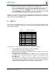
Figure 61
below is the design of the EEPROM circuit.
The EEPROM used is the same one as is used on the BeagleBone and the element14
BeagleBone Black, a CAT24C256. The CAT24C256 is a 256 kb Serial CMOS EEPROM,
internally organized as 32,768 words of 8 bits each. It features a 64−byte page write buffer
and supports the Standard (100 kHz), Fast (400 kHz) and Fast−Plus (1 MHz) I
2
C protocol.