
User Manual


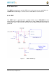

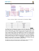


Figure 34 eMMC Memory Design
The pins used by the eMMC1 in the boot mode are listed below in
Table 5
.
Table 5 eMMC Boot Pins
For eMMC devices the ROM will only support raw mode. The ROM Code reads out raw
sectors from image or the booting file within the file system and boots from it. In raw
mode the booting image can be located at one of the four consecutive locations in the
main area: offset 0x0 / 0x20000 (128 KB) / 0x40000 (256 KB) / 0x60000 (384 KB). For this
reason, a booting image shall not exceed 128KB in size. However it is possible to flash
a device with an image greater than 128KB starting at one of the aforementioned
locations. Therefore the ROM Code does not check the image size. The only drawback is
that the image will cross the subsequent image boundary. The raw mode is detected by
reading sectors #0, #256, #512, #768. The content of these sectors is then verified for
presence of a TOC structure. In the case of a
GP Device
, a Configuration Header (CH)
must
be located in the first sector followed by a
GP header
. The CH might be void (only
containing a CHSETTINGS item for which the Valid field is zero).
The ROM only supports the 4-bit mode. After the initial boot, the switch can be made to
8-bit mode for increasing the overall performance of the eMMC interface.