
Data Sheet


RoboClaw Solo Motor Controller Data Sheet
(c) 2016 Basicmicro. All Rights Reserved.
6
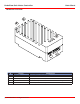
Logic Battery (LB IN)
The logic circuit of RoboClaw can be powered from a secondary battery wired to LB IN. A logic battery will prevent
brownouts when the main battery is low or under heavy load. The positive (+) terminal is located at the board edge and
ground (-) is the inside pin closest to the heatsink.
Encoder Inputs (1A / 1B)
The encoders input are labeled 1A and 1B. Quadrature encoder inputs are typically labeled 1A and 1B. Quadrature
encoders are directional. The encoder register will count up or down depending on the direction of rotation. Use Ion
Studio to determine the encoders direction to the motors rotation. Encoder channels A and B can be swapped in software
using Ion Studio to avoid re-wiring the encoder or motor.
Control Inputs (S1 / S2 / S3 / S4 /S5)
S1, S2, S3, S4 and S5 are congured for standard servo style headers I/O (except on ST models), +5V and GND. S1 and
S2 are the control inputs for serial, analog and RC modes. S3 can be used as a ip switch input, when in RC or Analog
modes. In serial mode S3, S4 and S5 can be used as emergency stops inputs or as voltage clamping control outputs.
When congured as E-Stop inputs, they are active when pulled low. All I/O have internal pull-ups to prevent accidental
triggers when left oating. S4 and S5 can be congured as home switch and limit switch inputs. The pins closest to the
board edge are the I/0s, center pin is the +5V and the inside pins are ground. Some RC receivers have their own supply
and will conict with the RoboClaw’s 5v logic supply. It may be necessary to remove the +5V pin from the RC receivers
cable in those situations.
Main Battery Wires
The main battery input rating is 6VDC to 34VDC. The RoboClaw Solo is pre-wired. The red wire is the positive (+)
connection and the black is the ground (-). 6VDC is the minimum voltage required to operate properly.
Do not reverse main battery wires or damage will occur.
Disconnect
The main battery should include a quick disconnect in case of a run away situation and power needs to be cut. The switch
must be rated to handle the maximum current and voltage from the battery. Total current will vary depending on the
type of motors used. A common solution would be an inexpensive contactor which can be sourced from sites like Ebay.
A power diode rated for approximately 2 to 10 Amps should be placed across the switch/contactor to provide a return to
the battery when power is disconnected. The diode will provide the regenerative power a place to go even if the switch is
open.
Motor Wires
The motor wires are color coded. The green wire is M1A and the yellow wire is M2B. The motor wires should be as short
as possible. Long wires can increase the inductance and therefore increase potentially harmful voltage spikes during
regenerative periods.
!