
User Manual


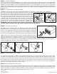

An overhead-lifting device, such as chain falls, engine hoist, or cable come-
a-long, can be used to lift the center section of the hitch in place. Lower a
loop of rope or chain through the 4” hole in the truck bed oor and attach it
to the latch pin in the round hitch receiver tube in the center section. Use
the lifting device to raise the center section until the round hitch receiver
tube that protrudes from the center section ts in the 4” hole in the truck
bed oor. Maintaining upward pressure may facilitate fastening the cross-
member to the center section, especially if the truck bed oor has been
distorted downward from heavy use. If you use an overhead-lifting device, it should be disconnected before
squaring the center section across the frame, installing the sideplates and torquing fasteners.
INSTALLATION INSTRUCTIONS
BALL LOCATION: 2007 Toyota Tundra 4” hole location 42
3
/
8
” All beds.
Important Information
Because of space restraints the 2007 Toyota Tundra mounting kit contains components that have
not been seen in any previous Turnoverball™ kits. For this reason it will not be possible to
store the ball in the inverted position. It also makes the 4” hole location very critical. It
is important to read the complete instruction sheet before beginning the installation.
STEP 1 – MARKING AND CUTTING 4 INCH HOLE IN TRUCK BED
Begin by measuring for the correct hole location in the truck bed oor. Measure from the tail gate end of
the truck bed oor by hooking a tape measure over the end of the truck box and mark the oor at 42
3
/
8
”.
Next nd the center point between the wheel wells, where these marks intersect with the rst measurement
will be the center point of your four inch hole. This location is critical to the correct installation of the B&W
Turnoverball™ hitch so measure, mark and saw carefully. Make a four-inch hole at this location. B&W recom-
mends using a four-inch hole saw, however the hole can be cut by other means. If your truck has a spray-
in bed liner you will need to take into account when you are measuring to add the thickness of the applied
liner that has been sprayed over the end of the bed. If your truck has a drop-in plastic bed liner, you may
saw through both, but it is more difcult to accurately locate the midpoint between the fender wheel wells,
and to be sure that the bed liner does not move when sawing the hole. Once you have the four-inch hole in
the bed use a deburring tool or a die grinder and carefully remove the burr from the underside of the bed
around the hole.
WARNING
Most trucks have FUEL LINES and/or BRAKE LINES and/or ELECTRICAL WIRES located along the frame rails
where B&W Turnoverball™ hitches install. Carefully examine the location of fuel lines, brake lines and elec-
trical wires BEFORE INSTALLATION. Be certain you will not damage fuel lines, brake lines or electrical wires
when positioning hitch components, drilling holes, tightening fasteners, and lifting and lowering the truck bed.
The fuel tank vent, located on top of the gas tank, can be easily damaged during the installation of the hitch
components. Care must be taken when positioning the front crossmember and center section components.
WARNING
On Short bed trucks, BEFORE INSTALLING THIS HITCH, check for adequate turning clearance between the
front of all of your trailers and the truck cab.
NOTICE:
At this time no accessories, including the model RVK3000 RV Companion 5th wheel hitch, will work with this model
of turnoverball™ except:
• 4” Toyota Hitch Extender (part# 4585)
• RV Companion 5th wheel hitch (model RVK3500),
with special socket post.
BEFORE INSTALLING- OVERHEAD LIFTING DEVICE