
User Guide


AXIS 2490 Getting Started Guide Page 2 of 5
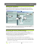
The Rear Panel
Network Connector
The AXIS 2490 is designed for 10
Mbps Ethernet and 100 Mbps
Fast Ethernet networks and con-
nects to the network via a
twisted pair category 5 cable
(10baseT and 100baseTX) termi-
nated using a standard RJ-45
connector. Supporting NWAY,
the AXIS 2490 detects the speed
of the local network segment
and varies the speed of data
communication accordingly,
between 10 Mbps and 100 Mbps.
Status Indicator
The yellow Status Indicator shows the unit’s operational
status, as described below:
• slow flash - indicates normal operation
• rapid flash - indicates a hardware failure
For the Status Indicator’s behavior during a reset to the
factory default settings, see page 4.
Physical Connections on the 8 pole I/O
Connector Block
(Phoenix MC 1.5 - 3.81mm)
4 pins for RS422/485 TX+, TX-, RX+, RX-
1 pin for RS485/422 ground (connected to
GND with 100 ohm resistor)
1 pin for GND
2 pins for alternative power (9-24V AC or DC)
The RS-485/422 port
A 4-wire RS-422/485 port (one TX pair and one combined RX/TX pair).
The RX port can be used for both RX and TX (controlled by RTS)
and can be used for half-duplex RS-485. The port can be used for:
• Full-duplex RS-422 (4-wire) or
• 4-wire RS-485 or
• Half-duplex RS-485 (2-wire)
The port is compliant with EIA RS-485 up to 1843200 bps.
Connections for RS-485/422 on Connector Block
1 - 9-24V AC or DC Power
2 - 9-24V AC or DC Power
3 - GND
4 - GND 100 Ohm (to GND via 100 Ohm resistor
5 - RX/TX -A
6 - RX/TX +B
7 - TX-
8 - TX+
Power Supply Connector
A single Jack socket (PS-B) for
connection of the AXIS 2490
power supply.
Power Indicator
Constantly lit = normal operation