
User's Manual


UHF Fibre-Fed Remote Site
User Handbook
Handbook N.-60-137601HBK Issue No:-1
Date:-18/03/2005
Page:-
30 of 38
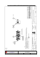
For small signals, below AGC onset, the output control line will be close to 12V and the
AGC attenuator will have minimum attenuation. As the signal level increases the control line
voltage will fall, increasing the attenuator value and keeping the system output level at a
constant value.
The AGC onset level is adjusted by the choice of sampler resistor R1 and by the setting of
potentiometer VR1, (factory set @ time of system test) do not adjust unless able to monitor
subsequent RF levels.
The attenuator comprises a 50 P.I.N diode, voltage-variable attenuator with a range of 3 to
30dB. The attenuation is controlled by a DC voltage which is derived from the associated
AGC detector unit.
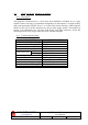
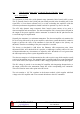
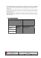
4.6.2 Technical Specification
PARAMETER SPECIFICATION
Frequency Range: up to 1000MHz
Attenuation Range: 3 to 30dB
Attenuation Steps: continuously variable
VSWR: better than 1.2:1
RF Connectors: SMA female
attenuator: 1W Power Handling:
detector/amp: >30W (or as required)
operation: -10°C to +60°C Temperature
Range:
storage: -20°C to +70°C
attenuator (pcb) 50 x 42 x 21mm Size:
Detector (pcb) 54 x 42 x 21mm
attenuator: 90grams Weight:
detector/amp: 100grams