
User's Manual


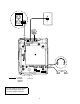


Table Of Contents
- 4606/4612/4624 IP Telephones Set Up Quick Reference
- Wall-Mounting Stand for 4400-Series Telephones and 4600-Series IP Telephones
- IMPORTANT SAFETY INSTRUCTIONS
- Pre-Installation Checklist
- Small Stand Wall-Mounting Instructions
- Wall Mounting the 4400-Series Telephone
- 1. Remove the handset hook from the handset cradle. Flip the hook 180 degrees and re-insert it so...
- 2. Insert the line cord into the line jack on the telephone and route the other end of the cord t...
- 3. Place the moveable tab on the thicker end of the stand into the slot at the bottom of the back...
- 4. Push down on the stand toward the top of the telephone, and push the tab on the thinner end of...
- 5. Plug the telephone’s line cord into the wall jack and store excess line cord in the open pocke...
- 6. Place the telephone against the wall so that the screwheads on the mounting plate enter the ho...
- Wall-Mounting the 4606 IP Telephone
- 1. Remove the handset hook from the handset cradle. Flip the hook 180 degrees and re-insert it so...
- 2. Place the moveable tab on the thicker end of the stand into the slot at the bottom of the back...
- 3. Push down on the stand toward the top of the telephone, and place the tab on the thinner end o...
- 4. Plug the telephone’s foot-long CAT 5 line cord into the primary Ethernet line interface jack (...
- 5. Place the other end of the line cord through the round hole in the middle of the stand, and sn...
- 6. If a connection to the Ethernet hub and secondary interface jack is required, plug the 14-foot...
- 7. Plug the line cord into the wall jack.
- 8. Place the 4606 IP telephone against the wall so that the screwheads on the mounting plate ente...
- 9. If the Ethernet hub line cord (step 6 above) is used, route it along the left side of the stan...
- Wall Mounting the 4400-Series Telephone
- Large Stand Wall-Mounting Instructions
- Wall Mounting the 4400-Series Telephone
- 1. Remove the handset hook from the handset cradle. Flip the hook 180 degrees and re-insert it so...
- 2. Insert the line cord into the line jack on the telephone and route the other end of the cord t...
- 3. Place the moveable tab on the thicker end of the stand into the slot at the bottom of the back...
- 4. Push down on the stand toward the bottom of the telephone, and push the tab on the thinner end...
- 5. After you have attached the stand to the telephone, use the screw provided to tighten the stan...
- 6. Plug the line cord into the wall jack and store the excess line cord in the open pocket space ...
- 7. Place the telephone against the wall so that the screwheads on the mounting plate enter the ho...
- Wall-Mounting the 4612/4624 IP Telephone with a Large Stand
- 1. Remove the handset hook from the handset cradle. Flip the hook 180 degrees and re-insert it so...
- 2. Place the moveable tab on the thicker end of the stand into the slot at the bottom of the back...
- 3. Push down on the stand toward the bottom of the telephone, and place the tab on the thinner en...
- 4. After you have attached the stand to the 4612/4624 IP telephone, use the screw provided to tig...
- 5. Plug the foot-long CAT 5 line cord into the primary Ethernet line interface jack (identified b...
- 6. Place the other end of the telephone’s line cord through the round hole in the middle of the t...
- 7. Plug the line cord into the wall jack.
- 8. Place the 4612/4624 IP telephone against the wall so that the screwheads on the mounting plate...
- 9. Use the notched corner on the back of the stand to fit the cord between the stand and wall.
- 10. If a connection to the Ethernet hub and secondary interface jack is required, plug the 14-foo...
- Wall Mounting the 4400-Series Telephone
- IMPORTANT SAFETY INSTRUCTIONS

1
CIB 3199
Comcode 108787698
Issue 2, November 2000
Wall-Mounting Stand for 4400-Series Telephones
and 4600-Series IP Telephones
IMPORTANT SAFETY INSTRUCTIONS
The exclamation point in an equilateral triangle is intended to alert the user to the
presence of important operating and maintenance (servicing) instructions in the literature
accompanying the product.
To reduce the risk of fire, electrical shock, and injury to persons, follow these basic safety precautions when
installing telephone equipment:
■
Read and understand all instructions.
■
Follow all warnings and instructions marked on or packed with the product.
■
Never install telephone wiring during a lightning storm.
■
Never install a telephone jack in a wet location unless the jack is specifically designed for wet locations.
■
Never touch uninsulated telephone wires or terminals unless the telephone wiring has been disconnected
at the network interface.
■
Use caution when installing or modifying telephone lines.
■
Use only an Avaya 4400-Series telephone Auxiliary Power Supply Unit (PEC 4499-PWR,
Comcode 108596412) with the 4424D+ (when connecting a DSS 4450).
■
Use only an Avaya 4600-Series telephone Local Power Supply Unit (PEC 1891-LPS,
Comcode 108737933), or Auxiliary Power Supply Unit (PEC 2404-012/A, Model 1151A2), or Bulk
Auxiliary Power Supply Unit (PEC 2404-011/A, Model 1145B) with the 4600-Series IP telephones.
■
Use only an Avaya-recommended/approved 4400- and 4600-Series telephone accessories.
■
Do not install this product near water, for example, in a wet basement location.
■
Do not overload wall outlets, as this can result in the risk of fire or electrical shock.
■
The 4400-Series and 4600-Series telephone Auxiliary Power Supply Units are equipped with a 3-wire
grounding-type plug with a third (grounding) pin. This plug will fit only into a grounding-type power outlet.
This is a safety feature. If you are unable to insert the plug into the outlet, contact an electrician to replace
the obsolete outlet. Do not defeat the safety purpose of the grounding plug.