
User's Manual


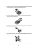


Table Of Contents
- 4606/4612/4624 IP Telephones Set Up Quick Reference
- Wall-Mounting Stand for 4400-Series Telephones and 4600-Series IP Telephones
- IMPORTANT SAFETY INSTRUCTIONS
- Pre-Installation Checklist
- Small Stand Wall-Mounting Instructions
- Wall Mounting the 4400-Series Telephone
- 1. Remove the handset hook from the handset cradle. Flip the hook 180 degrees and re-insert it so...
- 2. Insert the line cord into the line jack on the telephone and route the other end of the cord t...
- 3. Place the moveable tab on the thicker end of the stand into the slot at the bottom of the back...
- 4. Push down on the stand toward the top of the telephone, and push the tab on the thinner end of...
- 5. Plug the telephone’s line cord into the wall jack and store excess line cord in the open pocke...
- 6. Place the telephone against the wall so that the screwheads on the mounting plate enter the ho...
- Wall-Mounting the 4606 IP Telephone
- 1. Remove the handset hook from the handset cradle. Flip the hook 180 degrees and re-insert it so...
- 2. Place the moveable tab on the thicker end of the stand into the slot at the bottom of the back...
- 3. Push down on the stand toward the top of the telephone, and place the tab on the thinner end o...
- 4. Plug the telephone’s foot-long CAT 5 line cord into the primary Ethernet line interface jack (...
- 5. Place the other end of the line cord through the round hole in the middle of the stand, and sn...
- 6. If a connection to the Ethernet hub and secondary interface jack is required, plug the 14-foot...
- 7. Plug the line cord into the wall jack.
- 8. Place the 4606 IP telephone against the wall so that the screwheads on the mounting plate ente...
- 9. If the Ethernet hub line cord (step 6 above) is used, route it along the left side of the stan...
- Wall Mounting the 4400-Series Telephone
- Large Stand Wall-Mounting Instructions
- Wall Mounting the 4400-Series Telephone
- 1. Remove the handset hook from the handset cradle. Flip the hook 180 degrees and re-insert it so...
- 2. Insert the line cord into the line jack on the telephone and route the other end of the cord t...
- 3. Place the moveable tab on the thicker end of the stand into the slot at the bottom of the back...
- 4. Push down on the stand toward the bottom of the telephone, and push the tab on the thinner end...
- 5. After you have attached the stand to the telephone, use the screw provided to tighten the stan...
- 6. Plug the line cord into the wall jack and store the excess line cord in the open pocket space ...
- 7. Place the telephone against the wall so that the screwheads on the mounting plate enter the ho...
- Wall-Mounting the 4612/4624 IP Telephone with a Large Stand
- 1. Remove the handset hook from the handset cradle. Flip the hook 180 degrees and re-insert it so...
- 2. Place the moveable tab on the thicker end of the stand into the slot at the bottom of the back...
- 3. Push down on the stand toward the bottom of the telephone, and place the tab on the thinner en...
- 4. After you have attached the stand to the 4612/4624 IP telephone, use the screw provided to tig...
- 5. Plug the foot-long CAT 5 line cord into the primary Ethernet line interface jack (identified b...
- 6. Place the other end of the telephone’s line cord through the round hole in the middle of the t...
- 7. Plug the line cord into the wall jack.
- 8. Place the 4612/4624 IP telephone against the wall so that the screwheads on the mounting plate...
- 9. Use the notched corner on the back of the stand to fit the cord between the stand and wall.
- 10. If a connection to the Ethernet hub and secondary interface jack is required, plug the 14-foo...
- Wall Mounting the 4400-Series Telephone
- IMPORTANT SAFETY INSTRUCTIONS

11
9. Use the notched corner on the back of the stand to fit the cord between the stand and wall.
10. If a connection to the Ethernet hub and secondary interface jack is required, plug the 14-foot
CAT 5 line cord into the adjacent jack (identified by an icon on the right that looks like a stylized
PC).
Note: Make sure that you have routed the telephone handset cord out the side of the telephone,
using the trough and coil storage area.