Avaya Solution & Interoperability Test Lab Application Notes for the Hitachi Communication Technologies NT-SG with Avaya SIP Enablement Services and Avaya Communication Manager - Issue 1.0 Abstract These Application Notes describe the configuration of the Hitachi Communication Technologies NT-SG with an Avaya IP Telephony solution consisting of Avaya Communication Manager, Avaya SIP Enablement Services, Avaya 4600 Series H.323 Telephones, Avaya SP-1020A SIP Telephone, and Avaya one-X™ Desktop Edition.
1. Introduction These Application Notes describe the configuration of the Hitachi Communication Technologies NT-SG in an Avaya IP Telephony environment consisting of an Avaya SIP Enablement Services, Avaya Communication Manager, Avaya 4600 Series H.323 Telephones, Avaya SP-1020A SIP Telephone, and Avaya one-X™ Desktop Edition. The Hitachi Communication Technologies NT-SG is a session border controller that integrates signaling and media control for SIP.
Telephone numbers are assigned by the SIP telephony service provider. In these Application Notes, two numbers were assigned. One was “050-3380-4036” as a pilot number, which was registered with the Call Agent of the SIP telephony service provider through the SIP REGISTER message.
2. Equipment and Software Validated The following equipments and software were used for the configuration in Figure 1. Equipment Avaya SIP Enablement Services Avaya S8400 Media Server Avaya G600 Media Gateway C-LAN (TN799DP HW0) Media Processor (TN2302AP HW12) Avaya 4620SW IP Telephone Avaya SP-1020A SIP Telephone Avaya one-X Desktop Edition Hitachi Communication Technologies NT-SG Software 3.1, load 18.0 3.1.1, load 628.7 FW17 FW110 2.4 (H.323) 2.02.01 R2.
3. Configure Avaya Communication Manager This section describes the steps for configuring a SIP trunk on Avaya Communication Manager. The SIP trunk is established between Avaya Communication Manager and Avaya SIP Enablement Services (SES) server. This trunk will carry the SIP signaling and RTP voice packets sent to the Hitachi NT-SG.
Step 1 Confirm Necessary Optional Features Using the SAT, verify that there exist sufficient SIP Trunks and Off-PBX Telephones capacities by displaying the System-Parameters Customer-Options from shown in Figure 2. If a required feature is not enabled or there is insufficient capacity, contact an authorized Avaya sales representative to add additional capacity.
display system-parameters customer-options OPTIONAL FEATURES Page IP PORT CAPACITIES Maximum Administered H.323 Trunks: Maximum Concurrently Registered IP Stations: Maximum Administered Remote Office Trunks: Maximum Concurrently Registered Remote Office Stations: Maximum Concurrently Registered IP eCons: Max Concur Registered Unauthenticated H.323 Stations: Maximum Video Capable H.
Step 3 Define IP Network Region In the IP Network Region form, define the parameters associated with the SIP trunk group serving the Avaya SES proxy. • • • The Authoritative Domain field is configured to match the domain name configured on the Avaya SES. In this configuration, the domain name is alj.apac.avaya.com. By default, IP-IP Direct Audio is enabled to allow audio traffic to be sent directly between SIP endpoints without using media resources in the Avaya G600 Media Gateway.
Step 4 Define IP Codecs In the IP Codec Set form, define the ip-codec value specified in the IP Network Region from Figure 5. Although multiple codecs can be listed in priority order in this form, only G.711MU is shown in this case because the Hitachi NT-SG supports only G.711 mu-law. change ip-codec-set 1 Page 1 of 2 IP Codec Set Codec Set: 1 Audio Codec 1: G.
Step 5 Configure Signaling Group Configure the Signaling Group form using the “add signaling-group” command to add a new signaling group for SIP trunk between the Avaya Communication Manager and the Avaya SES server. • • • • • • Set the Group Type field to sip. The Transport Method field will default to tls (Transport Layer Security). TLS is the only link protocol that is supported for SIP trunking with Avaya SES. Specify the node names (i.e.
Step 6 Configure Trunk Group Configure the Trunk Group form using the “add trunk-group” command to add a new trunk group for the SIP trunk between the Avaya G600 Media Gateway and the Avaya SES server. On Page 1 of this form: • • • • Set the Group Type field to sip. Set the Service Type field to tie. Specify the signaling group associated with this trunk group in the Signaling Group field as previously specified in Figure 7 of Step 5. Specify the Number of Members supported by this SIP trunk group.
Step 7 Configure Calling Party Number Information Configure the Numbering Public/Unknown Format form to send the full calling party number to the far-end. This case assumes that: • The SIP telephony service provider assigns two telephone numbers, 050-3380-4036 and 050-3380-4037, to the enterprise site. All stations in the enterprise site have a 4-digit extension beginning with 20, 25 or 27. All outbound calls use SIP trunk group #50.
Step 8 Configure Route Pattern Configure the Route Pattern form to route calls to the SIP trunk. In the examples used in these Application Notes, the enterprise site, which was a subscriber of the SIP telephony service provider was assigned two telephone numbers beginning with 0 as well as other subscribers of the service provider. And all subscribers of the mobile communications SIP Service Providers and wireline telephone SIP Service Providers were assigned a telephone number beginning with 0 as well.
Step 9 Configure Incoming Digit Translation Configure the Incoming Call Handling Treatment form to map incoming DID calls to the proper extension. In the examples used in these Application Notes, the incoming numbers assigned by the SIP telephone service provider do not have a direct correlation to the internal extensions assigned within Avaya Communication Manager. Therefore all incoming called number digits are deleted and replaced by the assigned extension number.
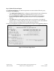
Figure 13: Avaya SES Administration Home Screen KN; Reviewed: SPOC 9/21/2006 Solution & Interoperability Test Lab Application Notes ©2006 Avaya Inc. All Rights Reserved.
Step 2 Define System Properties From the left pane of the Administration web interface, expand the Server Configuration option and select System Properties. • • • Enter the SIP Domain name assigned to Avaya SES. This is the same name that was entered in the Far-end Domain field shown in Figure 7. Enter the IP Address of the Avaya SIP Enablement Services server in License Host field as the WebLM application is running on it. After configuring the System Properties screen, click the Update button.
Step 4 nter Avaya SES Host Information Create a host computer entry for the Avaya SES. The following example shows the Edit Host screen since the host had already been added to the system. From the left pane, click the Hosts link and then click edit option under the Commands section of the subsequent page. • • • • • Enter the Logical IP or Logical Name (shown in Figure 14) of this server in the Host IP Address field.
Figure 15: Edit Host Screen KN; Reviewed: SPOC 9/21/2006 Solution & Interoperability Test Lab Application Notes ©2006 Avaya Inc. All Rights Reserved.
Step 5 Add Avaya Communication Manager as Media Server Interface Under the Media Servers option in the Administration web interface, select Add to add the Avaya Media Server. • • • • • Enter a descriptive name in the Media Server Interface Name field. Select the IP Address of the Avaya SES in the Host field. This was configured in the previous step. Select TLS for the SIP Trunk Link Type. TLS is the only link protocol that is supported for SIP trunking with Avaya Communication Manager.
This routing compares the Uniform Resource Identifier (URI) of an incoming SIP INVITE message to the pattern configured in the Media Server Address Map, and if there is a match, the call is routed to the designated Avaya Communication Manager. The URI usually takes the form of sip:user@domain, where domain can be a domain name or an IP address.
Figure 17: Add Media Server Address Map Screen for Avaya Communication Manager KN; Reviewed: SPOC 9/21/2006 Solution & Interoperability Test Lab Application Notes ©2006 Avaya Inc. All Rights Reserved.
After configuring the media server address map, the List Media Server Address Map screen appears as shown in Figure 18. Figure 18: List Media Server Address Map Screen The Media Server Contact is created automatically after the first Media Server Address Map is added. The user portion in the original request URI is substituted for $(user)of the SIP INVITE message going from Avaya SES to Avaya Communication Manager.
Step 7 Specify Address Maps to the Hitachi NT-SG As described in Step 8 of Section 3, in this configuration, all outbound calls originated from the extensions had the called number beginning with “9” (regardless of the following digits). Therefore only one dialing pattern of “^sip:9” will be needed. • • • • • • Access the Add Host Address Map screen by selecting the Hosts line in the left pane of the Administration web interface and then clicking on the Map link associated with Avaya SES.
Step 8 Specify the Hitachi NT-SG Host Contact Information Enter the contact address for the Hitachi NT-SG. In this example, the IP address 192.168.135.209 is used as shown in Figure 1. • • • • As described in Step 7, display the List Host Address Map screen. Click on the Add Another Contact link associated with the address map added in Figure 19 to open the Add Host Contact screen. In Figure 20, the Contact field specifies the destination for the call and it is entered as “sip:$(user)@192.168.135.
Figure 21: List Host Address Map Screen Step 9 Save the Changes Press the Update link. KN; Reviewed: SPOC 9/21/2006 Solution & Interoperability Test Lab Application Notes ©2006 Avaya Inc. All Rights Reserved.
Figure 22: Update Following SES Administrative Changes Step 10 Specify the Hitachi NT-SG as a Trusted Host Designate the IP address of the Hitachi NT-SG as a trusted host. As a trusted host, Avaya SES will not issue SIP authentication challenges for incoming requests from the designated IP address. • • Telnet to the Avaya SES IP address and log in using the administrative login and password. Enter the following trustedhost command at the Linux shell prompt: trustedhost -a 192.168.135.209 -n 192.168.135.
• Complete the trusted host configuration by returning to the main Avaya SES Administration web page and again clicking on the Update link as shown in Figure 22. admin@SES-01> trustedhost –a 192.168.135.209 –n 192.168.135.201 –c NT-SG 192.168.135.209 is added to trusted host list. admin@SES-01> trustedhost -L Third party trusted hosts. Trusted Host | CCS Host Name | Comment --------------------------+---------------------------+-----------------------192.168.135.209 | 192.168.135.
NT-SG ( 32ch) Module : Main Configuration (Main Menu) ---------------------------------| 1 | Command | ---------------------------------| 2 | Set Configuration | ---------------------------------| 3 | Change Configuration | ---------------------------------| 4 | Operating Condition | ---------------------------------| 5 | Logout | ---------------------------------- -------------------------------------------------------------------------------Selection: Down, Up, Enter Figure 24: Main Menu Screen Step 2 C
NT-SG ( 32ch) Module : Main Configuration (Set Configuration Module Select) ---------------------------------| 1 | Main Module | ---------------------------------| 2 | SIP Module 1 | ---------------------------------| 3 | SIP Module 2 | ---------------------------------- -------------------------------------------------------------------------------Selection: Tab, Down, Up, Enter Figure 25: Set Configuration Module Select Screen • Select the Main Module item and press the enter key.
The main module is capable of storing two configurations. In these Application Notes, Conf-1 was used for storing the configuration. • • Press the space key until the Conf-1 type is displayed at the Configuration Type field. Press the enter key and then the Conf Menu screen will appear as shown in Figure 27.
NT-SG ( 32ch) Module : Main Configuration (System Menu) ---------------------------------| 1 | Basic | ---------------------------------| 2 | Option | ---------------------------------- -------------------------------------------------------------------------------Selection: Tab, Down, Up, Enter Figure 28: System Menu Screen • • Select the Basic item and press the enter key. The System Basic1 form will appear. Press the enter key once to move to the System Basic2 form for the Port 1 (Figure 29).
NT-SG ( 32ch) Module : Main Configuration (System Basic2) Port1 IP Address :[192.168.135.209] Subnet Mask :[255.255.255.0 ] Default Gateway Primary :[192.168.135.
NT-SG ( 32ch) Module : Main Configuration (System Basic3) Port2 IP Address :[10.0.13.40 ] Subnet Mask :[255.255.255.0 ] Default Gateway Primary :[10.0.13.
NT-SG ( 32ch) Module : SIP1 Configuration (Type) Configuration Type:[ Conf-1 ] Current Current Current Current Configuration User Table No.Plan Calling Table : : : : Conf-1 User-1 No.Plan1 Calling1 -------------------------------------------------------------------------------Selection: Tab, Down, Up, Right, Left, Character, Enter Figure 31: Type Form of SIP Module Each SIP module is capable of storing two Configurations, two User Tables, two No.Plans and two Calling Tables.
NT-SG ( 32ch) Module : SIP1 Configuration (Conf Menu) ---------------------------------| 1 | SIP | ---------------------------------| 2 | DNS | ---------------------------------| 3 | Numbering | ---------------------------------| 4 | Option | ---------------------------------- -------------------------------------------------------------------------------Selection: Tab, Down, Up, Enter Figure 32: Conf Menu Screen of SIP Module NT-SG ( 32ch) Module : SIP1 Configuration (SIP Menu) --------------------------
• • • • Select the SIP Common Menu option and press the enter key. The SIP Common1 form will appear as shown in Figure 34. Specify the IP address of the Avaya SES to the 1st IP Address field. Return to the Type form (Figure 31) by using the tab key. Press the enter key and enter “y” to save the changes to the Hitachi NT-SG. NT-SG ( 32ch) Module : SIP1 Configuration (SIP Common1) SIP Server SIP Server :[ Used ] 1st IP Address :[192.168.135.
NT-SG ( 32ch) Module : SIP2 Configuration (Type) Configuration Type:[ Conf-1 ] Current Current Current Current Configuration User Table No.Plan Calling Table : : : : Conf-1 User-1 No.
NT-SG ( 32ch) Module : SIP2 Configuration (SIP Menu) ---------------------------------| 1 | SIP Common | ---------------------------------| 2 | SIP User | ---------------------------------| 3 | SIP Filtering | ---------------------------------- -------------------------------------------------------------------------------Selection: Tab, Down, Up, Enter Figure 37: SIP Menu Screen • • • Select the SIP Common and press the enter key. The SIP Common1 form will appear as shown in Figure 38.
NT-SG ( 32ch) Module : SIP2 Configuration (SIP Common1) SIP Server SIP Server :[ Used ] 1st IP Address :[10.0.113.3 ] 1st Domain Name :[cae.ds.
NT-SG ( 32ch) Module : SIP2 Configuration (SIP Common2) SIP System Invite Calling Number Set :[ System ] Privacy Header Scheme Set :[sip] Calling Number Notice :[ Notice ] Invite Arrival Mode :[ Normal ] Invite Expires Timer(s) :[300] Invite Redirect :[Off] Calling Number Get :[ Username ] Provisional Path Control :[On ] Invite Arrival Filtering :[Off] Slide Stop Control :[Off] Slide Stop Cause :[ ] [ ] [ ] Called Number Check :[After] Calling Number Control :[PRE] Called Number Mode :[Request] Dial 184/186
• • Press the enter key. The SIP User Common form will appear as shown in Figure 41. Specify the user ID and password, which are assigned by the SIP telephony service provider in advance, to register with the Call Agent of the SIP telephony service provider in the 1st User ID and 1st Password fields. In this example, the SIP telephony service provider assigned “user” and “passwd” as the user ID and password to the enterprise site.
NT-SG ( 32ch) Module : SIP2 User Configuration Info(Menu) ---------------------------------| 1 | Table | ---------------------------------- -------------------------------------------------------------------------------Selection: Tab, Down, Up, Enter Figure 42: Menu Screen for User Configuration Info of SIP Module • • • • • • • • Press the enter key. The User Info – Table No. 0001 form will appear as shown in Figure 43.
NT-SG ( 32ch) Module : SIP2 User Info (User Info - Table No. 0001) Info :[Used] Main :[M] Regist :[On] User Name :[05033804036 Display Name :[ Contact User Name :[ Del Column :[0 ] Add Number :[ Authorization Challenge Data 1st User ID :[ 1st Password :[ 2nd User ID :[ 2nd Password :[ Contact Parameter q :[ ] ] ] ] ] ] ] ] ] Display Screen :[Next] Table No.
NT-SG ( 32ch) Module : SIP2 User Info (User Info - Table No. 0002) Info :[Used] Main :[ ] Regist :[Off] User Name :[05033804037 Display Name :[ Contact User Name :[ Del Column :[0 ] Add Number :[ Authorization Challenge Data 1st User ID :[ 1st Password :[ 2nd User ID :[ 2nd Password :[ Contact Parameter q :[ ] ] ] ] ] ] ] ] ] Display Screen :[Next] Table No.
NT-SG ( 32ch) Module : SIP2 Configuration (Numbering Plan Menu) ---------------------------------| 1 | Table | ---------------------------------| 2 | Dest Information | ---------------------------------- -------------------------------------------------------------------------------Selection: Tab, Down, Up, Enter Figure 45: Numbering Plan Menu Screen • • • • • • Press the tab key to move the cursor to the parameter setting area. Move to the Del Column field of the Dial “9” using the arrow keys.
NT-SG ( 32ch) Module : SIP2 Configuration (Numbering Plan-Table No.
NT-SG ( 32ch) Module : Main Configuration (Change) Main Module Configuration change from Conf-1 to :[ Conf-1 ] SIP Module 1 Configuration change from User Table change from Table Pattern change from Calling Table change from Conf-1 User-1 No.Plan1 Calling1 to to to to :[ Conf-1 ] :[ None ] :[ None ] :[ None ] SIP Module 2 Configuration change from User Table change from Table Pattern change from Calling Table change from Conf-1 User-1 No.Plan1 Calling1 to to to to :[ Conf-1 ] :[ User-1 ] :[No.
• • • Service Provider network to the extensions in the enterprise site, and calls originated in the enterprise site to other participants through the SIP Service Provider network.
NT-SG provides enterprise customers with the cost effective converged network by integrating their telecommunication network with their broadband Internet access network. 10. Additional References 10.1. Documentation This section references the Avaya documentation relevant to these Application Notes. The following Avaya product documentation is available at http://support.avaya.com/. [1] Administrator Guide for Avaya Communication Manager, May 2006, Issue 2.1, Document Number 03-300509.
APPENDIX A: Sample SIP INVITE Messages This section displays the format of the SIP INVITE messages sent by the NT-SG and the Avaya SIP Enablement Services at the enterprise site. Customers may use these INVITE message for comparison and troubleshooting purposes. Differences in these messages may indicate different configuration options selected. Sample SIP INVITE Message from NT-SG to Avaya SIP Enablement Services: INVITE sip:05033804036@192.168.135.201;user=phone SIP/2.
Sample SIP INVITE Message from Avaya SIP Enablement Services to NT-SG: INVITE sip:905033804028@192.168.135.209;transport=udp SIP/2.0 Call-ID: 80a4751d627db12a1044a4fb2000 CSeq: 1 INVITE From: "Aomori 4620SW, " ;tag=80a4751d627db1291044a4fb2000 Record-Route: , To: "905033804028" Via: SIP/2.0/UDP 192.168.135.201:5060;branch=z9hG4bK838383030303161616479e.
©2006 Avaya Inc. All Rights Reserved. Avaya and the Avaya Logo are trademarks of Avaya Inc. All trademarks identified by ® and ™ are registered trademarks or trademarks, respectively, of Avaya Inc. All other trademarks are the property of their respective owners. The information provided in these Application Notes is subject to change without notice.