
Manual


COC-1 Self Contained Power
Connector Installation I
ns
tr
uc
t
i
ons
For 2 Wire Cable With Ground
A
pp
li
c
a
t
i
ons
The 2-circuit-with-ground connectors will splice non-metallic-sheathed cable in the following wire ranges and types:
Self Contained Connector
-
2 Circuit with ground for Solid
W
i
r
e
W
i
r
e
R
ange
A
WG
O
r
de
r
N
o
.
O
p
t
i
ona
l
Hand
T
oo
l
O
p
t
i
ona
l
B
en
c
h
M
oun
t
T
oo
l
O
p
t
i
ona
l
B
en
c
h
A
r
bo
r
P
r
e
ss
H
ou
s
i
ng
C
o
l
o
r
1
2
-
1
4
1
90
4
5
-
1
000
(C
O
C
-
1
)
1
9
2
8
5
-
00
7
4
N
/
A
6
4
006
-
0
2
00
W
h
i
t
e
Re
f
e
r
e
n
c
e I
n
f
o
r
m
a
t
i
on
UL File Number: E182087,
CSA File Number: LR18689-C53
NEC Article: 550, 551, and 545
HUD Section: 3280.801
Current:
20A,Voltage:
300V
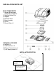
FIG. 2
Installation Procedure:
1. Carefully strip and prepare the wires to the
configuration
as shown in Figure 1 using helpful
hints shown in photographs of Figure 2.
2. Hold the clear strain relief cover with bottom facing upward as shown in Figure 3.
3. Lay wire into locator slots, making sure the black wire is placed into the polarization slot as
shown in Figure 3.
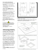
4. Press the cable sheath into the integral strain relief slot as shown in Figure 3. Trimming of
ground wire and possibly others will be necessary. Wires must not extend beyond the
locators as shown in Figure 4!
5. While holding the strain relief cover, position the housing’s hinge posts into the hinge slots
and press down until both lock into place as shown in Figure 4.
6. Close the strain relief cover and housing by hand. Place the connector assembly into Molex
tool (preferred) as shown in Figure 5. Squeeze the tool until the connector bottoms out and
the locking latches engage on both sides. OR alternately, squeeze the top and bottom
closed with tongue and groove pliers as shown in Figure 5.1. Pliers must be a minimum of
10" long. Squeeze
firmly on both sides, squarely across the connector between ribs A and B to ensure wires seat
completely into slots.
7. Inspect the connector to ensure the wires have been properly engaged into the housing
assembly contacts. A properly terminated wire is fully seated into its proper slots with no
significant bow of the cover. If the wires extend past the insulations tops, the wires must be
re-terminated with a
NEW CONNECTOR. Once
the cover has been closed the connector
cannot be re-used. Failure to comply with this procedure may result in the failure of the
connector.
8. Mating and un-mating the completed connector is illustrated in Figure 6.