
Datasheet


369
2549O–AVR–05/12
ATmega640/1280/1281/2560/2561
5)The sum of all IOH, for ports F0-F7, K0-K7 should not exceed 100mA.
If IOH exceeds the test condition, VOH may exceed the related specification. Pins are not guaranteed to source current
greater than the listed test condition.
5. Values with “PRR1 – Power Reduction Register 1” enabled (0xFF).
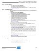
31.2 Speed Grades
Maximum frequency is depending on V
CC.
As shown in Figure 31-1 trough Figure 31-4 on page
370, the Maximum Frequency vs. V
CC
curve is linear between 1.8V < V
CC
< 2.7V and between
2.7V < V
CC
< 4.5V.
31.2.1 8MHz
Figure 31-1. Maximum Frequency vs. V
CC
, ATmega640V/1280V/1281V/2560V/2561V
Figure 31-2. Maximum Frequency vs. V
CC
when also No-Read-While-Write Section
(1)
,
ATmega2560V/ATmega2561V, is used
Note: 1. When only using the Read-While-Write Section of the program memory, a higher speed can
be achieved at low voltage, see “Read-While-Write and No Read-While-Write Flash Sections”
on page 317 for addresses.
8 MHz
4 MHz
1.8V 2.7V 5.5V
Safe Operating Area
8 MHz
2 MHz
1.8V 2.7V 5.5V
Safe Operating Area