USER GUIDE Atmel-ICE The Atmel-ICE Debugger Atmel-ICE is a powerful development tool for debugging and programming ® ® ® ® ARM Cortex -M based Atmel SAM and Atmel AVR microcontrollers with OnChip Debug capability.
Table of Contents The Atmel-ICE Debugger ............................................................. 1 1. Introduction .............................................................................. 4 1.1. 1.2. 1.3. Introduction to the Atmel-ICE ................................................... 4 Atmel-ICE Features ............................................................... 4 System Requirements ............................................................ 4 2. Getting Started with the Atmel-ICE ...
7. Command Line Utility ............................................................ 30 8. Advanced Debugging Techniques ........................................ 31 8.1. 8.2. Atmel AVR UC3 Targets ....................................................... 8.1.1. EVTI / EVTO Usage ................................................. debugWIRE Targets ............................................................. 8.2.1. Software Breakpoints ............................................... 31 31 31 31 9.
1. Introduction 1.1 Introduction to the Atmel-ICE Atmel-ICE is a powerful development tool for debugging and programming ARM Cortex-M based Atmel SAM and Atmel AVR microcontrollers with On-Chip Debug capability. It supports: 1.2 1.
The Atmel-ICE should be connected to the host computer using the USB cable provided, or a certified USBmicro cable.
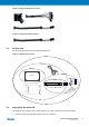
2. Getting Started with the Atmel-ICE 2.1 Full Kit Contents The Atmel-ICE full kit contains these items: ● Atmel-ICE unit ● USB cable (1.8m, high-speed, micro-B) ● Adapter board containing 50-mil AVR, 100-mil AVR/SAM and 100-mil 20-pin SAM adapters ● IDC flat cable with 10-pin 50-mil connector and 6-pin 100-mil connector ● 50-mil 10-pin mini squid cable with 10 x 100-mil sockets Figure 2-1. Atmel-ICE Full Kit Contents 2.
Figure 2-2. Atmel-ICE Basic Kit Contents 2.3 PCBA Kit Contents The Atmel-ICE PCBA kit contains these items: ● Atmel-ICE unit without plastic encaptulation Figure 2-3. Atmel-ICE PCBA Kit Contents 2.
Figure 2-4. Atmel-ICE Adapter Kit Contents Figure 2-5. Atmel-ICE Cable Kit Contents 2.5 Kit Overview The Atmel-ICE kit options are shown diagrammatically here: Figure 2-6. Atmel-ICE Kit Overview full kit basic kit PCBA kit adapter kit PCBA SAM AVR cable kit 2.6 Assembling the Atmel-ICE The Atmel-ICE unit is shipped with no cables attached.
● 50-mil 10-pin mini-squid cable with 10 x 100-mil sockets Figure 2-7. Atmel-ICE Cables For most purposes, the 50-mil 10-pin IDC flat cable can be used, connecting either natively to its 10-pin or 6pin connectors, or connecting via the adapter board. Three adapters are provided on one small PCBA. The following adapters are included: ● 100-mil 10-pin JTAG/SWD adapter ● 100-mil 20-pin SAM JTAG/SWD adapter ● 50-mil 6-pin SPI/debugWIRE/PDI/aWire adapter Figure 2-8.
Figure 2-10. Atmel-ICE AVR Probe Connection Figure 2-11. Atmel-ICE SAM Probe Connection 2.7 Note Opening the Atmel-ICE For normal operation, the Atmel-ICE unit must not be opened. Opening the unit is done at your own risk. Anti-static precautions should be taken. The Atmel-ICE enclosure consists of three separate plastic components - top cover, bottom cover and blue belt - which are snapped together during assembly.
Figure 2-12. Opening the Atmel-ICE (1) Figure 2-13.
Figure 2-14. Opening the Atmel-ICE(3) To close the unit again, simply align the top and bottom covers correctly, and press together firmly. 2.8 Powering the Atmel-ICE The Atmel-ICE is powered by the USB bus voltage. It requires less than 100mA to operate, and can therefore be powered through a USB hub. The power LED will illuminate when the unit is plugged in.
3. Connecting the Atmel-ICE 3.1 Overview: Connecting to AVR and SAM Target Devices The Atmel-ICE probe has two 50-mil 10-pin JTAG connectors accessible on the front of the tool's enclosure. Both connectors are directly electrically connected, but conform to two different pinouts - the AVR JTAG header and the ARM Cortex Debug header.
Note The JTAGICE3 100-mil adapter cannot be used with the SAM connector port, since pins 2 and 10 (AVR GND) on the adapter are connected. Connection to a custom 100-mil header If your target board does not have a compliant 10-pin JTAG header in 50- or 100-mil, you can map to a custom pinout using the 10-pin "mini-squid" cable (included in some kits), which gives access to ten individual 100-mil sockets.
3.4 Atmel-ICE AVR port pins Target pins Mini-squid pin aWire pinout Pin 3 (TDO) DATA 3 1 Pin 4 (VTG) VTG 4 2 Pin 5 (TMS) 5 Pin 6 (nSRST) 6 Pin 7 (Not connected) 7 Pin 8 (nTRST) 8 Pin 9 (TDI) 9 Pin 10 (GND) 0 Connecting to a PDI Target The recommended pinout for the 6-pin PDI connector is shown in Figure 4-6, “PDI Header Pinout” on page 22.
Connection to a 6-pin 50-mil SPI header Use the adapter board (included in some kits) to connect to a standard 50-mil SPI header. Connection to a custom 100-mil header The 10-pin mini-squid cable should be used to connect between the Atmel-ICE AVR connector port and the target board. Three connections are required, as described in Table 3-4, “Atmel-ICE debugWIRE Pin Mapping” on page 16.
Note The SPI interface is effectively disabled when the debugWIRE enable fuse (DWEN) is programmed, even if SPIEN fuse is also programmed. To re-enable the SPI interface, the 'disable debugWIRE' command must be issued while in a debugWIRE debugging session. Disabling debugWIRE in this manner requires that the SPIEN fuse is already programmed. If Atmel Studio fails to disable debugWIRE, it is probable that the SPIEN fuse is NOT programmed.
The ARM SWD interface is s subset of the JTAG interface, making use of TCK and TMS pins, which means that when connecting to an SWD device, the 10-pin JTAG connector can technically be used. The ARM JTAG and AVR JTAG connectors are however not pin-compatible, so this depends upon the layout of the target board in use. When using STK600 or a board making use of the AVR JTAG pinout, the AVR connector port on the Atmel-ICE must be used.
4. On-Chip Debugging 4.1 Introduction to On-Chip Debugging (OCD) A traditional Emulator is a tool which tries to imitate the exact behaviour of a target device. The closer this behaviour is to the actual device’s behaviour, the better the emulation will be. The Atmel-ICE is not a traditional Emulator. Instead, the Atmel-ICE interfaces with the internal On-Chip Debug system inside the target device, providing a mechanism for monitoring and controlling its execution.
When designing an application PCB which includes an Atmel AVR with the JTAG interface, it is recommended to use the pinout as shown in Figure 4-2, “AVR JTAG Header Pinout” on page 20. The Atmel-ICE can connect to both 100-mil and 50-mil variants of this pinout. Figure 4-2. AVR JTAG Header Pinout 1 2 TCK GND TDO VCC TMS /RESET (TRST) (NC) TDI GND AVR JTAG Table 4-1. AVR JTAG Pin Description Name Pin Description TCK 1 Test Clock (clock signal from the Atmel-ICE into the target device).
Name Pin Description VTG 1 Target voltage reference. The Atmel-ICE samples the target voltage on this pin in order to power the level converters correctly. The Atmel-ICE draws less than 3mA from this pin in debugWIRE mode and less than 1mA in other modes. GND 3, 5, 9 Ground. All must be connected to ensure that the Atmel-ICE and the target device share the same ground reference. KEY 7 Connected internally to TRST pin on the AVR connector. Recommended as not connected.
The aWire interface makes use the RESET wire of the AVR device to allow programming and debugging functions. A special enable sequence is transmitted by the Atmel-ICE which disables the default RESET functionality of the pin. When designing an application PCB which includes an Atmel AVR with the aWire interface, it is recommended to use the pinout as shown in Figure 4-5, “aWire Header Pinout” on page 22. The Atmel-ICE ships with both 100-mil and 50-mil adapters supporting this pinout. Figure 4-5.
In-System Programming uses the target Atmel AVR’s internal SPI (Serial Peripheral Interface) to download code into the flash and EEPROM memories. It is not a debugging interface. When designing an application PCB which includes an AVR with the SPI interface, the pinout shown in Figure 4-8, “SPI Header Pinout” on page 23 should be used. Figure 4-8. SPI Header Pinout PDO/MISO SCK /RESET 4.2.6 1 2 SPI VCC PDI/MOSI GND TPI TPI is a programming-only interface for some AVR ATtiny devices.
● Unlimited number of user program breakpoints (using BREAK) ● Real-time program counter branch tracing, data trace, process trace (not supported by Atmel-ICE) For special considerations regarding this debug interface, see “Atmel AVR UC3 OCD” on page 35. For more information regarding the UC3 OCD system, consult the AVR32UC Technical Reference Manuals, 1 located on www.atmel.com/uc3 . 4.3.
5. Hardware Description 5.1 LEDs The Atmel-ICE top panel has three LEDs which indicate the status of current debug or programming sessions. Table 5-1. LEDs LED Function Left Target power Middle Right 5.2 Main power Status Description GREEN when target power is OK. Flashing indicates a target power error. Does not light up until a programming/debugging session connection is started. RED when main-board power is OK. GREEN when the target is running. ORANGE when target is stopped.
5.4 Architecture Description The Atmel-ICE architecture is shown in the block diagram in Figure 5-1, “Atmel-ICE block diagram” on page 26. Figure 5-1. Atmel-ICE block diagram 5.4.1 Atmel-ICE Mainboard Power is supplied to the Atmel-ICE from the USB bus, regulated to 3.3V by a step-down switchmode regulator.
5.4.2 Atmel-ICE Target Connectors The Atmel-ICE does not have an active probe. A 50-mil IDC cable is used to connect to the target application either directly, or through the adapters included in some kits. For more information on the cabling and adapters, see section Assembling the Atmel-ICE 5.4.3 Atmel-ICE target Connectors Part Numbers In order to connect the Atmel-ICE 50-mil IDC cable directly to a target board, any standard 50-mil 10-pin header should suffice.
6. Software Integration 6.1 Atmel Studio 6.1.1 Software Integration in Atmel Studio Atmel Studio is an Integrated Development Environment (IDE) for writing and debugging Atmel AVR and Atmel SAM applications in Windows environments. Atmel Studio provides a project management tool, source file editor, simulator, assembler and front-end for C/C++, programming, emulation and on-chip debugging. Atmel Studio version 6.2 or later must be used in conjunction with the Atmel-ICE. 6.1.
Debug sessions on UC3 target devices over the aWire interface will be automatically tuned to the optimal baud rate by the Atmel-ICE itself. However, if you are experiencing reliability problems related to a noisy debug environment, it is possible to force the aWire speed below a configurable limit. Debug sessions on SAM target devices over the SWD interface can be clocked at up to ten times the CPU clock (but limited to 2MHz max).
7. Command Line Utility Atmel Studio comes with a command line utility called atprogram that can be used to program targets using the Atmel Atmel-ICE. During the Atmel Studio installation a shortcut called Atmel Studio 6.2 Command Prompt were created in the Atmel folder on the Start menu. By double clicking this shortcut a command prompt will be opened and programming commands can be entered. The command line utility is installed in the Atmel Studio installation path in the folder Atmel/Atmel Studio 6.
8. Advanced Debugging Techniques 8.1 Atmel AVR UC3 Targets 8.1.1 EVTI / EVTO Usage The EVTI and EVTO pins are not accessible on the Atmel-ICE. However, they can still be used in conjunction with other external equipment. EVTI can be used for the following purposes: ● The target can be forced to stop execution in response to an external event. If the Event In Control (EIC) bits in the DC register are written to 0b01, high-to-low transition on the EVTI pin will generate a breakpoint condition.
9. Special Considerations 9.1 Atmel AVR XMEGA OCD OCD and clocking When the MCU enters stopped mode, the OCD clock is used as MCU clock. The OCD clock is either the JTAG TCK if the JTAG interface is being used, or the PDI_CLK if the PDI interface is being used. I/O modules in stopped mode In contrast to earlier Atmel megaAVR devices, in XMEGA the I/O modules are stopped in stop mode. This means that USART transmissions will be interrupted, timers (and PWM) will be stopped.
corresponding bits set. The TXC (transmit complete) flag will be set and will be available on the next single step of the code even though it normally would happen later in an actual device.
See “Debug Options” on page 28 for details on how to set the target clock frequency using the software frontend. JTAGEN and OCDEN fuses The JTAG interface is enabled using the JTAGEN fuse, which is programmed by default. This allows access to the JTAG programming interface. Through this mechanism, the OCDEN fuse can be programmed (by default OCDEN is un-programmed). This allows access to the OCD in order to facilitate debugging the device.
Note If the SPIEN fuse was NOT left programmed, Atmel Studio will not be able to complete this operation, and high-voltage programming must be used. ● During a debug session, select the 'Disable debugWIRE and Close' menu option from the 'Debug' menu. DebugWIRE will be temporarily disabled, and Atmel Studio will use SPI programming to unprogram the DWEN fuse Having the DWEN fuse programmed enables some parts of the clock system to be running in all sleep modes.
SWD interface The RESET line should always be connected so that the Atmel-ICE can enable the SWD interface.
10. Firmware Upgrade For information on how to upgrade the firmware, see the Atmel Studio user guide in Atmel Studio (USER GUIDE).
11. Release History and Known issues 11.1 What's New Atmel-ICE is new! 11.2 Firmware Release History 11.2.1 Atmel Studio 6.2 Table 11-1. New in this Release 11.2.2 Release platform Atmel Studio 6.2 (final) Firmware version 1.13 New features None Fixes ● Fixed oscillator calibration command ● Improved debugWIRE reliability Atmel Studio 6.2 (beta)2 Table 11-2. New in this Release Release platform Atmel Studio 6.2 (beta) Firmware version 1.
12. Product Compliance 12.1 RoHS and WEEE The Atmel-ICE (all kits) and its accessories are manufactured in accordance to both the RoHS Directive (2002/95/EC) and the WEEE Directive (2002/96/EC). 12.
13. Document Revisions Document revision Date Comment 42330A 06/2014 Initial document for release.
Atmel Corporation T: (+1)(408) 441.0311 1600 Technology Drive, San Jose, CA 95110 USA F: (+1)(408) 436.4200 | www.atmel.com © 2014 Atmel Corporation. / Rev.: 42330A-MCU-07/2014 ® ® ® ® ® ® ® Atmel , Atmel logo and combinations thereof, Enabling Unlimited Possibilities , AVR , AVR Studio , megaAVR , tinyAVR , XMEGA , and others are registered ® ® ® trademarks or trademarks of Atmel Corporation in U.S. and other countries.