
User Manual


1-20
Chapter 1: Product Introduction
Chapter 1
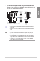
• System power LED (2-pin or 3-1 pin PLED)
The2-pinor3-1pinconnectorisforthesystempowerLED.Connectthechassis
powerLEDcabletothisconnector.ThesystempowerLEDlightsupwhenyouturnon
thesystempower,andblinkswhenthesystemisinsleepmode.
• Hard disk drive activity LED (2-pin HDD_LED)
This2-pinconnectorisfortheHDDActivityLED.ConnecttheHDDActivityLEDcable
tothisconnector.TheHDDLEDlightsuporasheswhendataisreadfromorwritten
totheHDD.
• System warning speaker (4-pin SPEAKER)
This4-pinconnectorisforthechassis-mountedsystemwarningspeaker.Thespeaker
allowsyoutohearsystembeepsandwarnings.
• ATX power button/soft-off button (2-pin PWRSW)
Thisconnectorisforthesystempowerbutton.Pressingthepowerbuttonturnsthe
systemonorputsthesysteminsleeporsoft-offmodedependingontheoperating
systemsettings.Pressingthepowerswitchformorethanfoursecondswhilethe
systemisONturnsthesystemOFF.
• Reset button (2-pin RESET)
This2-pinconnectorisforthechassis-mountedresetbuttonforsystemrebootwithout
turningoffthesystempower.
• Chassis intrusion connector (2-pin CHASSIS)
Thisconnectorisforachassis-mountedintrusiondetectionsensororswitch.Connect
oneendofthechassisintrusionsensororswitchcabletothisconnector.Thechassis
intrusionsensororswitchsendsahigh-levelsignaltothisconnectorwhenachassis
componentisremovedorreplaced.Thesignalisthengeneratedasachassisintrusion
event.
7. System panel connector (20-3 pin PANEL)
Thisconnectorsupportsseveralchassis-mountedfunctions.