
User Manual


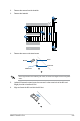


Table Of Contents
- Safety information
- Chapter 1: Product Introduction
- Chapter 2: Hardware Setup
- Chapter 3: Motherboard Information
- Chapter 4: BIOS Setup
- 4.1 Managing and updating your BIOS
- 4.2 BIOS setup program
- 4.3 Main menu
- 4.4 Advanced menu
- 4.4.1 CPU Configuration
- 4.4.2 Power & Performance
- 4.4.3 Server ME Configuration
- 4.4.4 System Event Log
- 4.4.5 Trusted Computing
- 4.4.6 Redfish Host Interface Settings
- 4.4.7 Onboard LAN Configuration
- 4.4.8 Serial Port Console Redirection
- 4.4.9 Intel TXT Information
- 4.4.10 SIO Configuration
- 4.4.11 PCI Subsystem Settings
- 4.4.12 USB Configuration
- 4.4.13 Network Stack Configuration
- 4.4.14 CSM (Compatibility Support Module)
- 4.4.15 NVMe Configuration
- 4.4.16 APM Configuration
- 4.4.17 Third-party UEFI driver configurations
- 4.5 Chipset menu
- 4.6 Security menu
- 4.7 Boot menu
- 4.8 Monitor menu
- 4.9 Tool menu
- 4.10 Event Logs menu
- 4.11 Server Mgmt menu
- 4.12 Exit menu
- Chapter 5: RAID Configuration
- Appendix

2-25
ASUS TS100-E11-PI4
2. Remove the screws from the heatsink.
3. Remove the heatsink.
3
2
2
2
2
2
Please pay attention when removing the screw, the stand screw might be removed together
with it.
Stand screw
Screw
M.2 slot
Screw hole
4. Remove the screw on the stand screw.
5. (optional) Remove the stand screw, then secure it to the screw hole of the M.2 card
length you wish to install an M.2 to.
6. Align and insert the M.2 card into the M.2 slot.