
User Manual


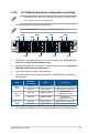


Table Of Contents
- Safety information
- Chapter 1: Product Introduction
- Chapter 2: Hardware Information
- 2.1 Chassis cover
- 2.2 Air ducts
- 2.3 Central Processing Unit (CPU)
- 2.4 System memory
- 2.5 (optional) Front bezel
- 2.6 Storage devices
- 2.7 Expansion slot
- 2.7.1 Installing an expansion card to riser card bracket 1 (for standard model)
- 2.7.2 Installing an expansion card to riser card bracket 2 and 3 (for standard model)
- 2.7.3 Installing a GPU card to riser card bracket 1 (for GPU model)
- 2.7.4 Installing a GPU card to riser card bracket 2 and 3 (for GPU model)
- 2.7.5 Installing an expansion card to riser bracket 4
- 2.7.6 Installing an ethernet expansion card to riser bracket 4
- 2.7.7 Replacing an HBA/RAID expansion card to riser bracket 4
- 2.7.8 Installing the Cache Vault Power Module
- 2.7.9 Installing an OCP 3.0 card
- 2.7.10 Installing an M.2 (NGFF) card
- 2.7.11 Configuring an expansion card
- 2.8 Cable connections
- 2.9 Backplane cabling
- 2.10 Storage device configuration and cabling
- 2.11 Removable/optional components
- 2.12 Rail Kit Options
- Chapter 3: Motherboard Information
- Chapter 4: BIOS Setup
- 4.1 Managing and updating your BIOS
- 4.2 BIOS setup program
- 4.3 Main menu
- 4.4 Performance Tuning menu
- 4.5 Advanced menu
- 4.5.1 Trusted Computing
- 4.5.2 Redfish Host Interface Settings
- 4.5.3 AMD CBS
- 4.5.4 Onboard LAN Configuration
- 4.5.5 Serial Port Console Redirection
- 4.5.6 CPU Configuration
- 4.5.7 PCI Subsystem Settings
- 4.5.8 USB Configuration
- 4.5.9 Network Stack Configuration
- 4.5.10 NVMe Configuration
- 4.5.11 SATA Configuration
- 4.5.12 APM Configuration
- 4.5.13 AMD Mem Configuration Status
- 4.5.14 T1s Auth
- 4.5.15 Driver Health
- 4.5.16 Third-party UEFI driver configurations
- 4.6 Chipset menu
- 4.7 Security menu
- 4.8 Boot menu
- 4.9 Tool menu
- 4.10 Event Logs menu
- 4.11 Server Mgmt menu
- 4.12 Exit menu
- Chapter 5: Driver Installation
- Appendix

Chapter 2: Hardware Information
2-62
1 2
3 4
RESET
SATA/SAS
SATA/SAS
SATA/SAS SATA/SAS
SATA/SAS
SATA/SAS
SATA/SAS
SATA/SAS
NVMe
NVMe
NVMe
NVMe
NVMe
2.10.3 8 x SATA/SAS + 4 x NVMe storage device
configuration and cabling
2. Remove the rear and backplane covers. For more information, refer to
Removing the
rear cover
and
Removing the backplane cover
.
3. Install the HBA/RAID card to your system. For more information, refer to
Replacing an
HBA/RAID expansion card to riser bracket 4
.
4. Locate the backplane, and then cut the cable tie(s).
5. Connect the cables to the motherboard, backplane, and HBA/RAID card according to
the table below.
Bays
Backplane
connector
Cable Connect to
Bays 1 - 4
(NVMe)
MCIO_P1 MCIO to MCIO MCIOPCIE1 on motherboard
MCIO_P2 MCIO to MCIO MCIOPCIE2 on motherboard
Bays 5 - 12
(SATA/SAS)
SLIMSAS1 SLIMSAS to SLIMSAS
HBA/RAID card
(1 x SLIMSAS connector)
SLIMSAS2 SLIMSAS to SLIMSAS
6. Tie the cables with cable tie(s) (A), then reinstall the backplane cover to the chassis (B).
1. Install the storage devices into the supported bays.
Refer to
Storage Devices
for details on how to install storage devices.
• The illustrations in this section are for reference only and may vary between models.
• This configuration requires an HBA/RAID card.