
User Manual


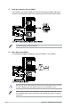


Table Of Contents
- Safety information
- Chapter 1: Product Introduction
- Chapter 2: Hardware Information
- 2.1 Chassis cover
- 2.2 Central Processing Unit (CPU)
- 2.3 System memory
- 2.4 Storage devices
- 2.5 Expansion slot
- 2.5.1 Installing an expansion card to riser card bracket 1
- 2.5.2 Installing an expansion card to riser card bracket 2
- 2.5.3 Installing an expansion card to riser card bracket 3 (for model without rear bay only)
- 2.5.4 Installing an expansion card to riser card bracket 4
- 2.5.5 Replacing the ASUS PIKE II card
- 2.5.6 Installing an ASUS PCIE-NVME4-OCuLink card
- 2.5.7 Replacing the ASUS PCIE-NVME2-OCuLink card (for model with rear bay only)
- 2.5.8 Configuring an expansion card
- 2.5.9 Installing Mezzanine cards
- 2.5.10 Installing M.2 (NGFF) cards
- 2.6 Cable connections
- 2.7 SATA/SAS backplane cabling
- 2.8 Removable/optional components
- Chapter 3: Installation Options
- Chapter 4: Motherboard Information
- Chapter 5: BIOS Setup
- 5.1 Managing and updating your BIOS
- 5.2 BIOS setup program
- 5.3 Main menu
- 5.4 Performance Tuning menu
- 5.5 Advanced menu
- 5.5.1 Trusted Computing
- 5.5.2 ACPI Settings
- 5.5.3 Smart Settings
- 5.5.4 Super IO Configuration
- 5.5.5 Serial Port Console Redirection
- 5.5.6 Onboard LAN Configuration
- 5.5.7 APM
- 5.5.8 PCI Subsystem Settings
- 5.5.9 USB Configuration
- 5.5.10 CSM Configuration
- 5.5.11 NVMe Configuration
- 5.5.12 Offboard SATA Controller Configuration
- 5.5.13 Network Stack Configuration
- 5.5.14 iSCSI Configuration
- 5.6 Platform Configuration menu
- 5.7 Socket Configuration menu
- 5.8 Event Logs menu
- 5.9 Server Mgmt menu
- 5.10 Security menu
- 5.11 Boot menu
- 5.12 Tool menu
- 5.13 Save & Exit menu
- Chapter 6: RAID Configuration
- Chapter 7: Driver Installation
- Appendix

Chapter 4: Motherboard Information
4-20
14. Chassis Intrusion (2-pin INTRUSION1)
These leads are for the intrusion detection feature for chassis with intrusion sensor or
microswitch. When you remove any chassis component, the sensor triggers and sends
a high level signal to these leads to record a chassis intrusion event. The default setting
is to short the CHASSIS# and the GND pin by a jumper cap to disable the function.
13. VGA connector (16-pin VGA_HDR1)
This connector supports the VGA High Dynamic-Range interface.