
User Manual

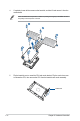


Table Of Contents
- Safety information
- Chapter 1: Product Introduction
- Chapter 2: Hardware Information
- 2.1 Chassis cover
- 2.2 Air ducts
- 2.3 Central Processing Unit (CPU)
- 2.4 System memory
- 2.5 (optional) Front bezel
- 2.6 Storage devices
- 2.7 Expansion slot
- 2.7.1 Installing an expansion card to riser card bracket 1 (for standard model)
- 2.7.2 Installing an expansion card to riser card bracket 2 and 3 (for standard model)
- 2.7.3 Installing a GPU card to riser card bracket 1 (for GPU model)
- 2.7.4 Installing a GPU card to riser card bracket 2 and 3 (for GPU model)
- 2.7.5 Installing an expansion card to riser bracket 4
- 2.7.6 Installing an ethernet expansion card to riser bracket 4
- 2.7.7 Replacing an HBA/RAID expansion card to riser bracket 4
- 2.7.8 Installing the Cache Vault Power Module
- 2.7.9 Installing an OCP 3.0 card
- 2.7.10 Installing an M.2 (NGFF) card
- 2.7.11 Configuring an expansion card
- 2.8 Cable connections
- 2.9 Backplane cabling
- 2.10 Storage device configuration and cabling
- 2.11 Removable/optional components
- 2.12 Rail Kit Options
- Chapter 3: Motherboard Information
- Chapter 4: BIOS Setup
- 4.1 Managing and updating your BIOS
- 4.2 BIOS setup program
- 4.3 Main menu
- 4.4 Performance Tuning menu
- 4.5 Advanced menu
- 4.5.1 Trusted Computing
- 4.5.2 ACPI Settings
- 4.5.3 Redfish Host Interface Settings
- 4.5.4 Onboard LAN Configuration
- 4.5.5 Serial Port Console Redirection
- 4.5.6 SIO Configuration
- 4.5.7 PCI Subsystem Settings
- 4.5.8 USB Configuration
- 4.5.9 Network Stack Configuration
- 4.5.10 NVMe Configuration
- 4.5.11 APM Configuration
- 4.5.12 Tls Auth Configuration
- 4.5.13 Intel(R) Virtual RAID on CPU
- 4.6 Platform Configuration menu
- 4.7 Socket Configuration menu
- 4.8 Security menu
- 4.9 Boot menu
- 4.10 Tool menu
- 4.11 Event Logs menu
- 4.12 Server Mgmt menu
- 4.13 Exit menu
- Chapter 5: Driver Installation
- Appendix

2-11
ASUS RS720-E11 Series
2.3.2 Removing the CPU and heatsink (for GPU model)
To install the CPU and heatsink:
1. Remove the rear cover. For more information, refer to
Chassis cover
.
2. Remove the air ducts. For more information, refer to
Air ducts
.
3. Push the lock latches inwards on all four corners of the heatsink, and then slightly twist
each of the heatsink screws counterclockwise in the order shown on the illustration to
loosen the heatsink.
Intel
®
recommends a torque value of 8 lbf-in to prolong the longevity of all PEEK nuts after
the quality of the load post is corrected.
Lock latches