
Owner's manual


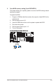

Table Of Contents
- About this guide
- Notices
- Safety information
- Chapter 1: Product introduction
- Chapter 2: Hardware setup
- Chapter 3: Installation options
- Chapter 4: Motherboard Info
- Chapter 5: BIOS setup
- Chapter 6: RAID configuration
- Chapter 7: Driver installation

Chapter 4: Motherboard information4-8
4. LAN controller setting (3-pin LAN_SW1, LAN_SW2)
These jumpers allow you to enable or disable the onboard Intel
®
Intel
82574LGigabit LAN controllers. Set to pins 1–2 to activate the Gigabit LAN
feature.
5. Chassis intrusion connector (2 pin CHASSIS)
This connector is for a chassis-mounted intrusion detection sensor or switch.
Connect one end of the chassis intrusion sensor or switch cable to this
connector. The chassis intrusion sensor or switch sends a high-level signal to
this connector when a chassis component is removed or replaced. The signal
is then generated as a chassis intrusion event.
By default , the pin labeled “Chassis Signal” and “Ground” are shorted with
a jumper cap. Remove the jumper caps only when you intend to use the
chassis intrusion detection feature.