
User Manual


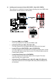


Table Of Contents
- Safety information
- Chapter 1: Product Introduction
- Chapter 2: Hardware Information
- 2.1 Chassis cover
- 2.2 Central Processing Unit (CPU)
- 2.3 System memory
- 2.4 Storage devices
- 2.5 Expansion slot
- 2.5.1 Installing an expansion card to the riser card bracket
- 2.5.2 Installing an expansion card to the butterfly riser card bracket
- 2.5.3 Installing an ASUS PIKE II card
- 2.5.4 Installing an ASUS PCIE-NVME2-OCuLink card to the butterfly riser card bracket (optional for RS700A-E9-RS12V2 only)
- 2.5.5 Installing an ASUS PCIE-NVME4-OCuLink card to the riser card bracket (optional for RS700A-E9-RS12V2 only)
- 2.5.6 Configuring an expansion card
- 2.5.7 Installing Mezzanine cards
- 2.5.8 Installing M.2 (NGFF) cards
- 2.6 Cable connections
- 2.7 Backplane cabling
- 2.8 Storage device configuration and cabling (for RS700A-E9-RS12V2 only)
- 2.8.1 8 x SATA storage device configuration and cabling
- 2.8.2 12 x SATA storage device configuration and cabling
- 2.8.3 8 x SATA/SAS and 4 x SATA storage device configuration and cabling
- 2.8.4 2 x NVMe storage device configuration and cabling
- 2.8.5 4 x NVMe storage device configuration and cabling
- 2.8.6 8 x NVMe storage device configuration and cabling
- 2.9 Removable/optional components
- Chapter 3: Installation Options
- Chapter 4: Motherboard Information
- Chapter 5: BIOS Setup
- 5.1 Managing and updating your BIOS
- 5.2 BIOS setup program
- 5.3 Main menu
- 5.4 Performance Tuning menu
- 5.5 Advanced menu
- 5.5.1 Trusted Computing
- 5.5.2 PSP Firmware Versions
- 5.5.3 APM Configuration
- 5.5.4 Onboard LAN Configuration
- 5.5.5 Serial Port Console Redirection
- 5.5.6 CPU Configuration
- 5.5.7 PCI Subsystem Settings
- 5.5.8 USB Configuration
- 5.5.9 CSM Configuration
- 5.5.10 NVMe Configuration
- 5.5.11 SATA Configuration
- 5.5.12 Network Stack Configuration
- 5.5.13 AMD Mem Configuration Status
- 5.5.14 iSCSI Configuration
- 5.6 Chipset menu
- 5.7 Security menu
- 5.8 Boot menu
- 5.9 Tool menu
- 5.10 Save & Exit menu
- 5.11 AMD CBS menu
- 5.12 Event Logs menu
- 5.13 Server Mgmt menu
- Chapter 6: Driver Installation
- Appendix

Chapter 4: Motherboard Information
4-14
5. USB 2.0 connector (10-1 pin USB67)
This connector is for USB 2.0 ports. Connect the USB module cable to the connector,
and then install the module to a slot opening at the back of the system chassis. The
USB connectors comply with USB 2.0 specification that supports up to 480 Mbps
connection speed.
6. Fan power connectors (FANPWR1-3)
These connectors are for the power supply plugs that connects to additional fans. The
power supply plugs are designed to fit these connectors in only one orientation. Find
the proper orientation and push down firmly until the connectors completely fit.
The USB port module is purchased separately.