
User Manual

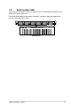


Table Of Contents
- Safety information
- Chapter 1: Product Introduction
- Chapter 2: Hardware Information
- 2.1 Chassis cover
- 2.2 Air ducts
- 2.3 Central Processing Unit (CPU)
- 2.4 System memory
- 2.5 Storage devices
- 2.6 Expansion slot
- 2.6.1 Installing an expansion card to the PCIe riser card bracket
- 2.6.2 Installing an OCP 3.0 slot baseboard and OCP 3.0 card to the PCIe riser card bracket
- 2.6.3 Installing an expansion card to the butterfly riser card bracket
- 2.6.4 Installing an ethernet expansion card to the butterfly riser card bracket
- 2.6.5 Installing an ASUS PIKE II card
- 2.6.6 Installing an M.2 (NGFF) card
- 2.6.7 Configuring an expansion card
- 2.7 Cable connections
- 2.8 Backplane cabling
- 2.9 Storage device configuration and cabling
- 2.10 Removable/optional components
- Chapter 3: Installation Options
- Chapter 4: Motherboard Information
- Chapter 5: BIOS Setup
- 5.1 Managing and updating your BIOS
- 5.2 BIOS setup program
- 5.3 Main menu
- 5.4 Performance Tuning menu
- 5.5 Advanced menu
- 5.5.1 Trusted Computing
- 5.5.2 PSP Firmware Versions
- 5.5.3 APM Configuration
- 5.5.4 Onboard LAN Configuration
- 5.5.5 Serial Port Console Redirection
- 5.5.6 CPU Configuration
- 5.5.7 PCI Subsystem Settings
- 5.5.8 USB Configuration
- 5.5.9 Network Stack Configuration
- 5.5.10 CSM Configuration
- 5.5.11 NVMe Configuration
- 5.5.12 SATA Configuration
- 5.5.13 AMD Mem Configuration Status
- 5.5.14 iSCSI Configuration
- 5.6 Chipset menu
- 5.7 Security menu
- 5.8 Boot menu
- 5.9 Tool menu
- 5.10 Save & Exit menu
- 5.11 AMD CBS menu
- 5.12 Event Logs menu
- 5.13 Server Mgmt menu
- Chapter 6: Driver Installation
- Appendix

ASUS RS700A-E11 Series
1-3
1.2 Serial number label
The product’s serial number contains 12 characters such as xxS0xxxxxxxx and printed on the
sticker at the server's front cover.
The correct serial number of the product is required if you need to request for support from
the ASUS Technical Support team.
xxS0xxxxxxxx
RS700A-E11-RS12U