
User Manual


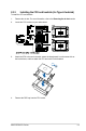


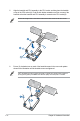
Table Of Contents
- Safety information
- Chapter 1: Product Introduction
- Chapter 2: Hardware Information
- 2.1 Chassis cover
- 2.2 Air duct(s)
- 2.3 Central Processing Unit (CPU)
- 2.4 System memory
- 2.5 (optional) Front bezel
- 2.6 Storage devices
- 2.7 Expansion slots
- 2.7.1 Installing an expansion card to the PCIe riser card bracket
- 2.7.2 Installing an OCP card
- 2.7.3 Installing an expansion card to the butterfly riser card bracket
- 2.7.4 Installing an ethernet expansion card to the butterfly riser card bracket
- 2.7.5 Installing an HBA/RAID card to the butterfly riser card bracket
- 2.7.6 Installing the Cache Vault Power Module
- 2.7.7 Installing an M.2 (NGFF) card
- 2.7.8 Configuring an expansion card
- 2.8 Cable connections
- 2.9 Backplane cabling
- 2.10 Storage device configuration and cabling
- 2.11 Removable/optional components
- 2.12 Rail Kit Options
- Chapter 3: Motherboard Information
- Chapter 4: BIOS Setup
- 4.1 Managing and updating your BIOS
- 4.2 BIOS setup program
- 4.3 Main menu
- 4.4 Performance Tuning menu
- 4.5 Advanced menu
- 4.5.1 Trusted Computing
- 4.5.2 ACPI Settings
- 4.5.3 Redfish Host Interface Settings
- 4.5.4 Onboard LAN Configuration
- 4.5.5 Serial Port Console Redirection
- 4.5.6 SIO Configuration
- 4.5.7 PCI Subsystem Settings
- 4.5.8 USB Configuration
- 4.5.9 Network Stack Configuration
- 4.5.10 NVMe Configuration
- 4.5.11 APM Configuration
- 4.5.12 Tls Auth Configuration
- 4.5.13 Intel(R) Virtual RAID on CPU
- 4.6 Platform Configuration menu
- 4.7 Socket Configuration menu
- 4.8 Security menu
- 4.9 Boot menu
- 4.10 Tool menu
- 4.11 Event Logs menu
- 4.12 Server Mgmt menu
- 4.13 Exit menu
- Chapter 5: Driver Installation
- Appendix

Chapter 2: Hardware Information
2-12
6. Do two (2) clockwise turns on each of the heatsink screws in the cross order pattern
shown on the illustration until the heatsink screws are tightened and the heatsink is
secured onto the motherboard.
Intel
®
recommends a using a torque driver with a T-30 bit and a torque value of 8 lbf-in to
prolong the longetivity of all PEEK nuts after the quality of the load post is corrected.
5. Align the heatsink and CPU assembly to the CPU socket, then place the heatsink on
top of the CPU socket (A). Push the lock latches outwards on all four corners of the
heatsink so that the heatsink and CPU assembly is secured to the CPU socket (B).
• Ensure the triangle mark on the CPU is located in the same corner as the CPU socket.
• The heatsink is symmetrical.
7. Replace the air duct. For more information, refer to the Replacing the air duct section.