
Manual


2-302-30
2-302-30
2-30
Chapter 2: Hardware informationChapter 2: Hardware information
Chapter 2: Hardware informationChapter 2: Hardware information
Chapter 2: Hardware information
10.10.
10.10.
10.
IEEE 1394b IEEE 1394b
IEEE 1394b IEEE 1394b
IEEE 1394b
port port
port port
port
connectors (10-1 pin IE1394B_1,connectors (10-1 pin IE1394B_1,
connectors (10-1 pin IE1394B_1,connectors (10-1 pin IE1394B_1,
connectors (10-1 pin IE1394B_1,
IE1394B_2IE1394B_2
IE1394B_2IE1394B_2
IE1394B_2
[purple] [purple]
[purple] [purple]
[purple]
))
))
)
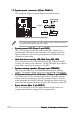
These connectors are for IEEE 1394b ports. Connect the IEEE 1394b
module cable (purple) to this connector, then install the module to a
slot opening at the back of the system chassis. Refer to the IEEE
1394b driver information on page 5-9 for details.
11.11.
11.11.
11.
GAME/MIDI port connector (16-1 pin GAME1)GAME/MIDI port connector (16-1 pin GAME1)
GAME/MIDI port connector (16-1 pin GAME1)GAME/MIDI port connector (16-1 pin GAME1)
GAME/MIDI port connector (16-1 pin GAME1)
This connector is for a GAME/MIDI port. Connect the USB/GAME
module cable to this connector, then install the module to a slot
opening at the back of the system chassis. The GAME/MIDI port
connects a joystick or game pad for playing games, and MIDI devices
for playing or editing audio files.
You can connect an optional IEEE 1394a module cable to these
connectors.
P5AD2-E
PREMIUM
®
P5AD2-E PREMIUM IEEE 1394 connectors
IE1394B_2
1
TPA1-
GND
TPB1-
+12V
GND
TPA1+
GND
TPB1+
+12V
IE1394B_1
1
TPA2-
GND
TPB2-
+12V
GND
TPA2+
GND
TPB2+
+12V
Never connect a
USB cable USB cable
USB cable USB cable
USB cable to the IEEE 1394b connectors.
Doing so will damage the motherboard!
P5AD2-E
PREMIUM
®
P5AD2-E PREMIUM GAME connector
GAME1
+5V
+5V
J2B1
J2CX
MIDI_OUT
J2CY
J2B2
MIDI_IN
J1B1
J1CX
GND
GND
J1CY
J1B2
+5V