
Manual


1-20 Chapter 1: Product Introduction
P 4 V 8 X - M X
R
CD(Black) AUX(White)
Right Audio Channel
Left Audio Channel
Ground
Ground
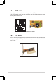
P4V8X-MX Internal Audio Connectors
P 4 V 8 X - M X
GND
USB_P7+
USB_P7-
USB+5V
NC
GND
USB_P8+
USB_P8-
USB+5V
R
USB56
1
USB78
USB+5V
USB_P8-
USB_P8+
GND
NC
USB+5V
USB_P7-
USB_P7+
GND
1
P4V8X-MX USB 2.0 Connectors
5. USB connectors (10-1 pin USB56, USB78)
These connectors are for USB 2.0 ports. Connect the USB module cable to
any of these connectors, then install the module to a slot opening at the back
of the system chassis.
The USB module is purchased separately.
Never connect a 1394 cable to the USB connectors. Doing so will damage the
motherboard!
6. Internal audio connectors (4-pin CD, AUX)
These connectors allow you to receive stereo audio input from sound sources
such as a CD-ROM, TV tuner, or MPEG card.