Series Motherboard NCCH-DR
E1679 First Edition V1 August 2004 Copyright © 2004 ASUSTeK COMPUTER INC. All Rights Reserved. No part of this manual, including the products and software described in it, may be reproduced, transmitted, transcribed, stored in a retrieval system, or translated into any language in any form or by any means, except documentation kept by the purchaser for backup purposes, without the express written permission of ASUSTeK COMPUTER INC. (“ASUS”).
Contents Notices ................................................................................................ vi Safety information ............................................................................. vii About this guide ............................................................................... viii Typography ......................................................................................... ix NCCH-DR Series specifications summary .............................................
Contents Chapter 3: Powering up 3.1 Starting up for the first time ................................................ 3-1 3.2 Powering off the computer .................................................. 3-2 3.2.1 3.2.2 Using the OS shut down function ........................... 3-2 Using the dual function power switch .................... 3-2 Chapter 4: BIOS Setup 4.1 Managing and updating your BIOS ........................................ 4-1 4.2 4.1.1 Creating a bootable floppy disk ................
Contents 4.6 Boot menu .......................................................................... 4-38 4.7 4.6.1 Boot Device Priority .............................................. 4-38 4.6.2 Hard Disk Boot Priority ......................................... 4-39 4.6.3 Removable Device Priority .................................... 4-39 4.6.4 CD-ROM Boot Priority ........................................... 4-40 4.6.5 Boot Settings Configuration ................................. 4-40 4.6.6 Security ........
Notices Federal Communications Commission Statement This device complies with Part 15 of the FCC Rules. Operation is subject to the following two conditions: • This device may not cause harmful interference, and • This device must accept any interference received including interference that may cause undesired operation. This equipment has been tested and found to comply with the limits for a Class B digital device, pursuant to Part 15 of the FCC Rules.
Safety information Electrical safety • To prevent electrical shock hazard, disconnect the power cable from the electrical outlet before relocating the system. • When adding or removing devices to or from the system, ensure that the power cables for the devices are unplugged before the signal cables are connected. If possible, disconnect all power cables from the existing system before you add a device.
About this guide This user guide contains the information you need when installing and configuring the motherboard. How this guide is organized This manual contains the following parts: • Chapter 1: Product introduction This chapter describes the features of the motherboard and the new technology it supports. • Chapter 2: Hardware information This chapter lists the hardware setup procedures that you have to perform when installing system components.
Conventions used in this guide To make sure that you perform certain tasks properly, take note of the following symbols used throughout this manual. D A N G E R / W A R N I N G : Information to prevent injury to yourself when trying to complete a task. C A U T I O N : Information to prevent damage to the components when trying to complete a task. I M P O R T A N T : Instructions that you MUST follow to complete a task. N O T E : Tips and additional information to help you complete a task.
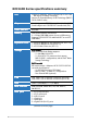
NCCH-DR Series specifications summary CPU Support for dual Intel® Xeon™ Processors up to 4.
NCCH-DR Series specifications summary Internal connectors Floppy disk drive connector IDE connectors Serial ATA connectors Serial ATA RAID connectors (SATA models only) Hard disk activity LED connector CPU and system fan connectors USB port connector SSI power connectors Serial port connector Printer port connector Backplane SMBus connector Power supply SMBus connector BMC connector Auxiliary panel connector System panel connector Industry standard PCI 2.3, PCI-X 1.0, USB 2.0 Manageability WfM 2.0.
xii
This chapter describes the motherboard features and the new technologies it supports.
Chapter summary 1 1.1 Welcome! .............................................................................. 1-1 1.2 Package contents ................................................................. 1-1 1.3 Special features ....................................................................
1.1 Welcome! T h a n k y o u f o r b u y i n g t h e A S U S® N C C H - D R m o t h e r b o a r d ! The ASUS NCCH-DR motherboard delivers a host of new features and latest technologies making it another standout in the long line of ASUS quality motherboards! Before you start installing the motherboard, and hardware devices on it, check the items in your package with the list below. 1.2 Package contents Check your motherboard package for the following items.
1.3 Special features 1.3.1 Product highlights Latest processor technology The motherboard comes with dual 604-pin surface mount ZIF sockets designed for the Intel® Xeon™ processor with 800 MHz Front Side Bus (FSB) and 1 MB L2 cache. The processor incorporates the Intel® Hyper-Threading Technology, the Intel® NetBurst™ micro-architecture that features hyper-pipelined technology, and Extended Memory 64-bit Technology (EM64T).
Dual Gigabit LAN solution The Intel® PRO/1000 CT Network Connection allows full-duplex Gigabit performance on LAN on Motherboard (LOM) applications through the Communication Streaming Architecture (CSA). Instead of connecting to the PCI bus, the controller connects to the dedicated CSA bus on the Memory Controller Hub (MCH) thus reducing the PCI bottlenecks by freeing the PCI bus for other I/O operations. The Intel® PRO/1000 MT Network Connection is also onboard to support 32-bit LAN through the PCI bus.
1.3.2 Innovative ASUS features ASUS CrashFree BIOS 2 This feature allows you to restore the original BIOS data from the support CD in case when the BIOS codes and data are corrupted. This protection eliminates the need to buy a replacement ROM chip. See page 4-7 for details. ASUS EZ Flash BIOS With the ASUS EZ Flash, you can easily update the system BIOS even before loading the operating system. No need to use a DOS-based utility or boot from a floppy disk. See page 4-9 for details.
This chapter lists the hardware setup procedures that you have to perform when installing system components. It includes description of the jumpers and connectors on the motherboard.
Chapter summary 2 2.1 Before you proceed .............................................................. 2-1 2.2 Motherboard overview .......................................................... 2-2 2.3 Central Processing Unit (CPU) ............................................ 2-13 2.4 System memory ................................................................. 2-16 2.5 Expansion slots ................................................................... 2-19 2.6. Jumpers ........................
2.1 Before you proceed Take note of the following precautions before you install motherboard components or change any motherboard settings. • Unplug the power cord from the wall socket before touching any component. • Use a grounded wrist strap or touch a safely grounded object or to a metal object, such as the power supply case, before handling components to avoid damaging them due to static electricity. • Hold components by the edges to avoid touching the ICs on them.
2.2 Motherboard overview Before you install the motherboard, study the configuration of your chassis to ensure that the motherboard fits into it. Make sure to unplug the chassis power cord before installing or removing the motherboard. Failure to do so can cause you physical injury and damage motherboard components. 2.2.1 Placement direction When installing the motherboard, make sure that you place it into the chassis in the correct orientation.
2.2.3 CPU heatsink weight support For additional protection from motherboard breakage due to the weight of the CPU heatsinks, your motherboard package comes with two solution kits. • X-PAD accessory kit containing: – 2 x metal support plates – 1 x contour sheet – 3 different sets of metal nuts and rubber pads for varied chassis standoffs (each set contains 8 metal nuts and 2 rubber pads) • 2 x CEK spring You can use any of the two solutions to protect the motherboard.
4. Use a plier to attach four nuts to the bolts on the metal support plate. 5. Align a rubber pad to the rectagular mark on the center of the plate, then press to attach. 6. 2-4 Remove the adhesive label underneath a plate.
7. Carefully align and place the plate on a rectangular cut on the contour sheet. Make sure that the metal support plates fit perfectly to the rectangular cuts on the contour sheet; otherwise, the CPU heatsink screws would not align to the metal nuts. 8. Repeat steps 4 and 7 to prepare and install the second plate. 9. Remove the contour sheet from the chassis.
The support plates appear as shown when installed. 9. Install the motherboard with the external I/O ports toward the chassis rear panel. The CPU sockets should be right on top of the support plates. Heatsink hole matched to a nut on the support plate Make sure that the CPU heatsink holes on the motherboard perfectly match the metal nuts on the support plates; otherwise, you can not install the CPU heatsinks properly. 10. Secure the motherboard with 9 screws. Refer to section “2.2.
Using the CEK springs Two CEK springs come with the motherboard package. You can also use these springs to support the weight of the CPU heatsinks. Take note of the four CEK spring hooks located beside the screw holes. CEK spring hook To install the CEK spring: 1. Locate the CPU heatsink holes on the motherboard. 2. Position the CEK spring underneath the motherboard, then match the CEK spring hooks to the CPU1 heatsink holes. 3.
4. Press the lower spring hooks inward, then insert to the lower CPU heatsink holes until they snap in place. 5. Repeat the process to install the second spring to the CPU2 heatsink holes. The support plates appear as shown when installed. 6. Install the motherboard with the external I/O ports toward the chassis rear panel. The CPU sockets should be right on top of the CEK springs. Heatsink hole matched to the hole on the CEK spring 7. 2-8 Secure the motherboard with 9 screws. Refer to section “2.
2.2.4 Motherboard layout IDE model 26.8cm (10.5in) ATX12V1 ATXPWR1 mPGA 604 PS/2KBMS T: Mouse KBPWR1 B: Keyboard PSUSMB1 USB12 USBPW12 COM1 REAR_FAN2 LAN_EN1 Intel CPU2 82547GI Gigabit Ethernet Intel mPGA 604 CPU_FAN2 FM_CPU2 DDR DIMM_A1 (64 bit,184-pin module) LAN1 DDR DIMM_A2 (64 bit,184-pin module) LAN2 DDR DIMM_B1 (64 bit,184-pin module) CPU1 DDR DIMM_B2 (64 bit,184-pin module) 30.
SATA model 26.8cm (10.5in) ATX12V1 ATXPWR1 mPGA 604 PS/2KBMS T: Mouse KBPWR1 B: Keyboard PSUSMB1 USB12 USBPW12 COM1 REAR_FAN2 LAN_EN1 Intel CPU2 82547GI Gigabit Ethernet Intel mPGA 604 CPU_FAN2 FM_CPU2 DDR DIMM_A1 (64 bit,184-pin module) LAN1 DDR DIMM_A2 (64 bit,184-pin module) LAN2 DDR DIMM_B1 (64 bit,184-pin module) CPU1 DDR DIMM_B2 (64 bit,184-pin module) 30.
2.2.5 Layout contents Slots Page 1. CPU sockets 2-13 2. DDR DIMM sockets 2-16 3.
Internal connectors 2-12 Page Floppy disk drive connector (34-1 pin FLOPPY) 2-27 IDE connectors (40-1 pin PRI_IDE, SEC_IDE) 2-27 Serial ATA connectors (7-pin SATA1, SATA2) 2-28 Serial ATA RAID connectors (7-pin SATA_RAID1, SATA_RAID2, SATA_RAID3, SATA_RAID4) SATA models only 2-29 Hard disk activity LED connector (2-pin HDLED) 2-29 CPU and system fan connectors (4-pin CPU_FAN1/2, 3-pin REAR_FAN1/2, FRNT_FAN1/2) 2-30 USB port connector (10-1 pin USB34) 2-30 SSI power connectors (24-pin ATXPWR
2.3 Central Processing Unit (CPU) The motherboard comes with a surface mount 604-pin Zero Insertion Force (ZIF) sockets. The sockets are designed for the Intel® Xeon™ processor in the 604-pin package with 1 MB L2 cache. The new generation Xeon™ processor supports 800 MHz system bus and EM64T. 2.3.1 Installling the CPU To install a CPU: 1. Locate the CPU sockets on the motherboard.
3. Position the CPU above the socket as shown. 4. Carefully insert the CPU into the socket until it fits in place. The CPU fits only in one correct orientation. DO NOT force the CPU into the socket to prevent bending the pins and damaging the CPU! Marked corner (gold arrow) 5. Carefully push down the socket lever to secure the CPU. The lever clicks on the side tab to indicate that it is locked. 6. Apply the thermal interface material (thermal grease) to the top of the CPU.
2.3.2 Installing the CPU heatsink(s) The Intel® Xeon™ processors require specially-designed passive heatsinks to provide optimum thermal condition and performance. Visit the ASUS website (www.asus.com) for an updated list of qualified heatsinks tested for use on this motherboard. Make sure that you have applied the thermal grease to the top of the CPU before installing the heatsink. To install the CPU heatsink and fan: 1.
2.4 System memory 2.4.1 Overview The motherboard comes with four Double Data Rate (DDR) Dual Inline Memory Modules (DIMM) sockets. The following figure illustrates the location of the DDR DIMM sockets: 104 Pins 80 Pins DIMM_A1 DIMM_A2 DIMM_B1 NCCH-DR DIMM_B2 NCCH-DR 184-Pin DDR DIMM sockets 2.4.2 Memory configurations You may install 128 MB, 256 MB, 512 MB and 1 GB unbuffered ECC or non-ECC DDR DIMMs into the DIMM sockets.
Table 1: Recommended memory configurations Mode DIMM_A1 (black) Sockets DIMM_A2 DIMM_B1 (blue) (black) DIMM_B2 (blue) Single-channel (1) Populated — — — (DDR400/DDR333) (2) — Populated — — (3) — — Populated — (4) — — — Populated Dual-channel (1) Populated — Populated — (DDR400/DDR333) (2) — Populated — Populated (3)* Populated Populated Populated Populated * For dual-channel configuration (3), you may: • install identical DIMMs in all four sockets, or • install ide
2.4.3 Installing a DIMM Unplug the power supply before adding or removing DIMMs or other system components. Failure to do so can cause severe damage to both the motherboard and the components. DDR DIMM notch To install a DIMM: 1. Unlock a DIMM socket by pressing the retaining clips outward. 2. Align a DIMM on the socket such that the notch on the DIMM matches the break on the socket. Unlocked retaining clip A DDR DIMM is keyed with a notch so that it fits in only one direction.
2.5 Expansion slots In the future, you may need to install expansion cards. The following sub-sections describe the slots and the expansion cards that they support. Make sure to unplug the power cord before adding or removing expansion cards. Failure to do so may cause you physical injury and damage motherboard components. 2.5.1 Installing an expansion card To install an expansion card: 1.
2.5.
2.6. 1. Jumpers Clear RTC RAM (CLRTC1) This jumper allows you to clear the Real Time Clock (RTC) RAM in CMOS. You can clear the CMOS memory of date, time, and system setup parameters by erasing the CMOS RTC RAM data. The onboard button cell battery powers the RAM data in CMOS, which include system setup information such as system passwords. To erase the RTC RAM: 1. Turn OFF the computer and unplug the power cord. 2. Remove the onboard battery. 3. Move the jumper cap from pins 1-2 (default) to pins 2-3.
2. CPU fan pin selection (3-pin FM_CPU1, FM_CPU2) These jumpers allow you to connect either a 3-pin or a 4-pin CPU fan cable plug to the CPU fan connectors (CPU_FAN1, CPU_FAN2). Set these jumpers to pins 1-2 if you are using a 3-pin fan cable plug, or to pins 2-3 if you are using a 4-pin plug. FM_CPU2 2 1 DC mode (Default) 3 2 PWM FM_CPU1 2 3 1 2 NCCH-DR DC mode (Default) PWM NCCH-DR FM_CPU Setting 3.
4. Keyboard power (3-pin KBPWR1) This jumper allows you to enable or disable the keyboard wake-up feature. Set this jumper to pins 2-3 (+5VSB) to wake up the computer when you press a key on the keyboard (the default is the Space Bar). This feature requires an ATX power supply that can supply at least 1A on the +5VSB lead, and a corresponding setting in the BIOS. KBPWR1 1 2 2 3 +5V (Default) +5VSB NCCH-DR NCCH-DR Keyboard power setting 5.
6. SATA controller LED setting (3-pin 8130LED1) This jumper allows you to enable or disable the SATA controller LED indicator in the chassis front panel. HDLED RECOVERY 8130 LED1 PANEL1 8130 LED1 1 2 NCCH-DR 2 3 Disable (Default) Enable NCCH-DR 8130 LED setting 7. Gigabit LAN controller setting (3-pin LAN_EN1; LAN_EN2) These jumpers allow you to enable or disable the onboard Gigabit LAN controllers.
8. Integrated graphics controller (3-pin VGA_EN1) This jumper allows you enable or disable the onboard graphics controller. VGA_EN1 1 2 Enable (Default) NCCH-DR 2 3 Disable NCCH-DR VGA Setting 9. Force BIOS recovery (3-pin RECOVERY) This jumper allows you to update or recover the BIOS settings when it gets corrupted or destroyed.This jumper allows you to update/recover the BIOS quickly. To update the BIOS: 1. Prepare a floppy disk that contains the latest BIOS for the motherboard (xxxx-xxx.
2.7 Connectors 2.7.1 Rear panel connectors 1 2 3 4 5 6 7 P S / 2 m o u s e p o r t ( g r e e n ) . This port is for a PS/2 mouse. P S / 2 k e y b o a r d p o r t ( p u r p l e ) . This port is for a PS/2 keyboard. U S B 2 . 0 p o r t s 1 a n d 2 . These two 4-pin Universal Serial Bus (USB) ports are available for connecting USB 2.0 devices. 1. 2. 3. S e r i a l ( C O M 1 ) p o r tt. This 9-pin communication port is for pointing devices or other serial devices. V G A p o r tt.
2.7.2 1. Internal connectors Floppy disk drive connector (34-1 pin FLOPPY) This connector is for the provided floppy disk drive (FDD) signal cable. Insert one end of the cable to this connector, then connect the other end to the signal connector at the back of the floppy disk drive. Pin 5 on the connector is removed to prevent incorrect cable connection when using a FDD cable with a covered Pin 5. FLOPPY PIN 1 NOTE: Orient the red markings on the floppy ribbon cable to PIN 1.
3. Serial ATA connectors (7-pin SATA1, SATA2) These connectors are for the Serial ATA signal cables for Serial ATA hard disk drives. If you installed Serial ATA hard disk drives, you can create a RAID 0 or RAID 1 configuration with the Intel® Matrix Storage Technology through the onboard Intel® 6300ESB integrated RAID controller. These connectors are set to S t a n d a r d I D E mode by default. In S t a n d a r d I D E mode, you can connect Serial ATA boot/data hard disk drives to these connectors.
4. Serial ATA RAID connectors (7-pin SATA_RAID1, SA TA_RAID2, SATA_RAID3, SATA_RAID4) On SATA models only ATA_RAID2, These connectors are for Serial ATA signal cables. These connectors support up to four Serial ATA hard disk drives that you can configure as a disk array through the Adaptec AIC-8130 SATA RAID controller.
6. CPU and system fan connectors (4-pin CPU_FAN1/2, 3-pin REAR_FAN1/2, FRNT_FAN1/2) The fan connectors support cooling fans of 350 mA ~ 740 mA (8.88 W max.) or a total of 2.1 A ~ 4.44 A (53.28 W max.) at +12V. Connect the fan cables to the fan connectors on the motherboard, making sure that the black wire of each cable matches the ground pin of the connector. Do not forget to connect the fan cables to the fan connectors. Insufficient air flow inside the system may damage the motherboard components.
S S I power connectors (24-pin ATXPWR1, 8 8-- p i n A T X 1 2 V 1 1)) These connectors are for SSI power supply plugs. The power supply plugs are designed to fit these connectors in only one orientation. Find the proper orientation and push down firmly until the connectors completely fit. • Use of an SSI 12 V Specification 2.0-compliant power supply unit (PSU) that provides a minimum power of 450 W is recommended for a fully-configured system.
9. Serial port connector (10-1 pin COM2) This connector is for a serial (COM) port. Connect the serial port module cable to this connector, then install the module to a slot opening at the back of the system chassis. COM2 PIN 1 NCCH-DR NCCH-DR Serial port2 (COM2) connector The serial port module is purchased separately. AFD# ERROR# PINIT# SLIN# GND GND GND GND GND GND GND GND 1 0 . Printer port connector (26-1 pin LPT1) This connector is for a parallel printer port.
1 1 . Backplane SMBus connector (6-1 pin BPSMB1) This connector allows you to connect SMBus (System Management Bus) devices. Devices communicate with an SMBus host and/or other SMBus devices using the SMBus interface. BPSMB1 NCCH-DR SMBus connector GND I2C_6_DATA# +5V NCCH-DR FAN_PWM I2C_6_CLK# 1 1 2 . Power supply SMBus connector (5-pin PSUSMB1) This connects SMBus (System Management Bus) devices to the power supply unit.
+5VSB +5VSB BMC_LANCLK# BMC_SMBCLK# PSON# BMC_RSTBTN# PWROK PSONEN 1 3 . BMC connector (16-pin BMCCONN1) This connector is for the optional ASUS server management card. 1 BMCCONN1 +5VSB +5VSB BMC_LANDATA# BMC_SMBDATA# BMC_PWRBTN# PRESENCE# SMIOUT# GND 2 NCCH-DR NCCH-DR BMC connector 1 4 .
1 5 . System panel connector (20-pin PANEL1) This connector supports several chassis-mounted functions. Message LED SPEAKER PLED+ NC PLEDMLED+ MLEDNC +5V GND GND SPKROUT Power LED NMIBTN# GND PWRBTN# GND NC FP_RESET# GND HDLED+ GND PANEL1 HDD LED NCCH-DR NCCH-DR System panel connector NMI Button RESET PWRSW The sytem panel connector is color-coded for easy connection. Refer to the connector descriptions on the next page for details.
2-36 Chapter 2: Hardware information
This chapter describes the power up sequence, the vocal POST messages, and ways of shutting down the system.
Chapter summary 3 3.1 Starting up for the first time ................................................ 3-1 3.2 Powering off the computer ..................................................
3.1 Starting up for the first time 1. After making all the connections, replace the system case cover. 2. Be sure that all switches are off. 3. Connect the power cord to the power connector at the back of the system chassis. 4. Connect the power cord to a power outlet that is equipped with a surge protector. 5. Turn on the devices in the following order: a. Monitor b. External SCSI devices (starting with the last device on the chain) c. System power 6.
3.2 Powering off the computer 3.2.1 Using the OS shut down function If you are using Windows® 2000: 2. Click the S t a r t button then click S h u t D o w n . . . Make sure that the S h u t D o w n option button is selected, then click the O K button to shut down the computer. 3. The power supply should turn off after Windows® shuts down. 1. If you are using Windows® XP: 2. Click the S t a r t button then select T u r n O f f C o m p u t e r .
This chapter tells how to change the system settings through the BIOS Setup menus. Detailed descriptions of the BIOS parameters are also provided.
Chapter summary 4 4.1 Managing and updating your BIOS ........................................ 4-1 4.2 BIOS Setup program ........................................................... 4-13 4.3 Main menu .......................................................................... 4-16 4.4 Advanced menu .................................................................. 4-20 4.5 Power menu ........................................................................ 4-32 4.6 Boot menu .....................
4.1 Managing and updating your BIOS The following utilities allow you to manage and update the motherboard Basic Input/Output System (BIOS) setup. 1. 2. 3. 4. A w a r d B I O S Flash Utility (Updates the BIOS in DOS mode using a floppy disk.) A S U S C r a s h F r e e B I O S 2 (Updates the BIOS using a bootable floppy disk or the motherboard support CD when the BIOS file fails or gets corrupted.) A S U S E Z F l a s h (Updates the BIOS in DOS mode using a floppy disk or the motherboard support CD.
Windows® 2000 environment To create a set of boot disks for Windows® 2000: a. Insert a formatted, high density 1.44 MB floppy disk into the drive. b. Insert the Windows® 2000 CD to the optical drive. c. Click S t a r tt, then select R u n n. d. In the O p e n field, type D:\bootdisk\makeboot a: assuming that D is your optical drive letter. e. Press , then follow screen instructions to continue. 2. 4-2 Copy the original or the latest motherboard BIOS file to the bootable floppy disk.
4.1.2 AwardBIOS Flash Utility The Basic Input/Output System (BIOS) can be updated using the AwardBIOS Flash Utility. The following sections tell you how to update the BIOS or how to save the current BIOS file. Updating the current BIOS file To update the current BIOS file: 1. Download the latest BIOS file from the ASUS web site. Extract the zipped file, then save it to a floppy disk as * . B I N N. Save only the updated BIOS file in the floppy disk to avoid loading the wrong BIOS file. 2.
6. Type the BIOS file name in the File Name to Program field, then press . AwardBIOS Flash Utility for ASUS V1.05 (C) Phoenix Technologies Ltd. All Rights Reserved For Canterwood - NCCH-DRC-00 Flash Type - SST 49LF008A /3.3V DATE: 07/14/2004 File Name to Program : 1001.bin Message: Do You Want To Save BIOS (Y/N) 7. The utility prompts you to save the current BIOS file. Press to save the current BIOS file to the floppy disk, or to continue.
Copying the current BIOS file You can use the AwardBIOS Flash Utility to save the current BIOS file. You can load the current BIOS file when the BIOS file gets corrupted during the flashing process. To save the current BIOS file using the AwardBIOS Flash Utility: 1. Follow steps 1 to 6 of the previous section. 2. Press when the utility prompts you to save the current BIOS file. The following screen appears. AwardBIOS Flash Utility for ASUS V1.05 (C) Phoenix Technologies Ltd.
4. The utility saves the current BIOS file to the floppy disk, then returns to the BIOS flashing process. AwardBIOS Flash Utility for ASUS V1.05 (C) Phoenix Technologies Ltd. All Rights Reserved For Canterwood - NCCH-DRC-00 Flash Type - SST 49LF008A /3.3V DATE: 07/14/2004 File Name to Program : 1001.
4.1.3 ASUS CrashFree BIOS 2 utility The ASUS CrashFree BIOS 2 is an auto recovery tool that allows you to restore the BIOS file when it fails or gets corrupted during the updating process. You can update a corrupted BIOS file using the motherboard support CD or the floppy disk that contains the updated BIOS file. Prepare the motherboard support CD or the floppy disk containing the updated motherboard BIOS before using this utility.
Recovering the BIOS from the support CD To recover the BIOS from the support CD: 1. Remove any floppy disk from the floppy disk drive, then turn on the system. 2. Insert the support CD to the optical drive. 3. The utility displays the following message and automatically checks the floppy disk for the original or updated BIOS file. Bad BIOS checksum. Starting BIOS recovery... Checking for floppy...
4.1.4 ASUS EZ Flash utility The ASUS EZ Flash feature allows you to update the BIOS without having to go through the long process of booting from a floppy disk and using a DOS-based utility. The EZ Flash utility is built-in the BIOS chip so it is accessible by pressing + during the Power-On Self Tests (POST). To update the BIOS using EZ Flash: 1. Visit the ASUS website (www.asus.com) to download the latest BIOS file for the motherboard. 2.
4.1.5 ASUS Update utility The ASUS Update is a utility that allows you to manage, save, and update the motherboard BIOS in Windows® environment. The ASUS Update utility allows you to: • Save the current BIOS file • Download the latest BIOS file from the Internet • Update the BIOS from an updated BIOS file • Update the BIOS directly from the Internet, and • View the BIOS version information. This utility is available in the support CD that comes with the motherboard package.
Updating the BIOS through the Internet To update the BIOS through the Internet: 1. Launch the ASUS Update utility from the Windows® desktop by clicking Start > Programs > ASUS > ASUSUpdate > ASUSUpdate e. The ASUS Update main window appears. 2. Select U p d a t e B I O S f r o m t h e I n t e r n e t option from the drop-down menu, then click N e x tt. ASUS NCCH-DR 3. Select the ASUS FTP site nearest you to avoid network traffic, or click A u t o S e l e c tt. Click N e x tt.
4. From the FTP site, select the BIOS version that you wish to download. Click Next. 5. Follow the screen instructions to complete the update process. The ASUS Update utility is capable of updating itself through the Internet. Always update the utility to avail all its features. Updating the BIOS through a BIOS file To update the BIOS through a BIOS file: 1. 2.
4.2 BIOS Setup program This motherboard includes a Flash ROM that you can update using the provided utility described in section “4.1 Managing and updating your BIOS.” Use the BIOS Setup program when you are installing a motherboard, reconfiguring your system, or prompted to “Run Setup”. This section explains how to configure your system using this utility. Even if you are not prompted to use the Setup program, you may want to change the configuration of your computer in the future.
4.2.1 BIOS menu screen Menu bar Menu items General help System Time System Date 11: 10 : 30 Wed, Jul 21 2004 Legacy Diskette A Floppy 3 Mode Support [1.44M, 3.5 in.] [Disabled] Primary IDE Master Primary IDE Slave Secondary IDE Master Secondary IDE Slave Third IDE Master Fourth IDE Master [None] [None] [None] [None] [None] [None] Base Memory Extended Memory Total Memory 640K 260096K 261120K Select Menu Item Specific Help Navigation keys 4.2.2 Change the internal clock.
4.2.4 General help On the right side of the menu screen is a brief description of the selected item. 4.2.5 Sub-menu An item with a sub-menu on any menu screen is distinguished by a solid triangle before the item. To display the sub-menu, select the item and press . 4.2.6 Scroll bar A scroll bar appears on the right side of a menu screen when there are items that do not fit on the screen.
4.3 Main menu When you enter the BIOS Setup program, the Main menu screen appears giving you an overview of the basic system information. Refer to section “4.2.1 BIOS menu screen” for information on the menu screen items and how to navigate through them. System Time System Date 11: 10 : 30 Wed, Jul 21 2004 Legacy Diskette A Floppy 3 Mode Support [1.44M, 3.5 in.
4.3.1 Primary IDE Master Primary Master Primary IDE Master Access Mode [Auto] [Auto] Capacity Cylinder Head Precomp Landing Zone Sector PIO Mode UDMA Mode Transfer Mode S.M.A.R.T Status Select Menu 0 MB 0 0 0 0 0 [Auto] [Auto] None None Item Specific Help Selects the type of fixed disk connected to the system. ‘Manual’ will let you select the number of cylinders, heads, etc. Note: PRECOMP=65535 means none! Primary IDE Master [Auto] Select [Auto] to automatically detect an IDE drive.
UDMA Mode [Auto] When this item is set to [Auto], the UDMA capability allows improved transfer speeds and data integrity for supported IDE drives. Configuration options: [Disabled] [Auto] Manually detecting an IDE drive If you wish to manually enter the drive information, set the Primary IDE Master item to [Manual], and the Access Mode item to [CHS]. Primary Master Primary IDE Master Access Mode Capacity Cylinder Head Precomp Landing Zone Sector PIO Mode UDMA Mode Transfer Mode S.M.A.R.
Head Shows the number of the hard disk read/write heads. Precomp Displays the precompressed volumes on the hard disk, if any, on the motherboard. Landing Zone Displays the drive’s maximum usable capacity as calculated by the BIOS based on the drive information you entered. Sector Shows the number of sectors per track. Transfer Mode Shows the data transfer mode if the IDE hard disk drive supports the feature. Otherwise, this item is grayed out and shows the value [None]. S.M.A.R.T.
4.4 Advanced menu The Advanced menu items allow you to change the settings for the CPU, memory, chipset, and other system devices. Take caution when changing the settings of the Advanced menu items. Incorrect field values may cause the system to malfunction! Advanced BIOS Features CPU Configuration Memory Configuration Chipset Onboard Device PCIPnP USB Configuration 4-20 Select Menu Item Specific Help Virus Protection, Boot Sequence...
4.4.1 Advanced BIOS Features This menu shows the console redirection and agent information. Select an item then press to display a pop-up menu with the configuration options. Advanced BIOS Features Console Redirection Baud Rate Agent Address Agent after boot [Disabled] 19200 [Auto] [Disabled] Select Menu Item Specific Help Enabled - Attempt to redirect console via COM port. Disabled - Attempt to redirect console when keyboard is absent.
4.4.2 CPU Configuration This menu shows the CPU configuration settings. Select an item then press to display a pop-up menu with the configuration options. CPU Configuration CPU L1 & L2 Cache Hyper-Threading Technology [Enabled] [Enabled] Select Menu Item Specific Help Disable/Enable CPU L1 L2 cache. CPU L1 & L2 Cache [Enabled] Allows you to enable or disable the CPU L1 and L2 cache.
4.4.3 Memory Configuration This menu shows the memory configuration settings. Select an item then press to display a pop-up menu with the configuration options. Memory Configuration DRAM Frequency Memory Timing Selectable Cache Latency Time Active to Precharge Delay DRAM RAS# to CAS# Delay DRAM RAS# Precharge Memory Parity Check [Auto] [By SPD] 3 8 4 4 Disabled Select Menu Item Specific Help Set DRAM Frequency. DRAM Frequency [Auto] This item sets the DRAM operating frequency.
DRAM RAS# Precharge [3] This item controls the idle clocks after issuing a precharge command to the DDR SDRAM. Configuration options: [4] [3] [2] Memory Parity Check [Enabled] Allows memory parity checking option. This item is not user-configurable and set to [Enabled] by default. 4.4.4 Chipset This menu shows the chipset configuration settings. Select an item then press to display a sub-menu with additional items, or show a popup menu with the configuration options.
4.4.5 Onboard Device This menu shows the onboard device configuration settings. Select an item then press to display a sub-menu with additional items, or show a pop-up menu with the configuration options. Onboard Device H/W Jumper of CSA LAN Onboard CSA LAN Boot ROM H/W Jumper of ONB LAN Onboard LAN Boot ROM Super I/O Device SATA Configuration Enabled [Disabled] Enabled [Disabled] Select Menu Item Specific Help Enable/Disable Onboard CSA LAN device boot ROM support.
Super I/O Device Super I/O Device Serial Port1 Address Serial Port2 Address Onboard Parallel Port Parallel Port Mode EPP Mode Select ECP Mode Use DMA [3F8/IRQ4] [2F8/IRQ3] [378/IRQ7] [SPP] EPP1.7 3 Select Menu Item Specific Help Set Base I/O address for serial port 1. Serial Port 1 [3F8/IRQ4] Serial Port 2 [2F8/IRQ3] Allow you to select the serial port base addresses.
SATA Configuration SATA Configuration *** On-Chip Serial ATA Setting *** On-Chip Serial ATA [Auto] SATA Mode IDE Serial ATA Port0 Mode SATA0 master Serial ATA Port1 Mode SATA1 master Select Menu Item Specific Help [Disabled]: Disable SATA Controller. [Auto]: Auto-arrange the BIOS. [Combined Mode]: PATA and SATA are combined. Max. of 2 IDE drives on each channel. [Enhanced Mode]: Enable both SATA and PATA. Max. of 6 IDE drives are supported. [SATA Only]: SATA is opeating in legacy mode.
SATA Mode [IDE] When set to [RAID], this item allows configuration of the installed IDE devices into a disk array. Configuration options: [IDE] [RAID] Serial ATA Port0 Mode [SATA0 master] Serial ATA Port1 Mode [SATA1 master] Allow you to set the SATA Port0 and Serial ATA Port1 modes. The options for these items vary depending on the setting of the O n - C h i p S e r i a l A T A item.
4.4.6 PCIPnP This menu shows the PCIPnP configuration settings. Select an item then press to display a pop-up menu with the configuration options. PCIPnP Select Menu Reset Configuration Data [Disabled] Item Specific Help Resources Controlled By IRQ Resources [Auto] PCI/VGA INT Pin INT Pin INT Pin INT Pin INT Pin INT Pin INT Pin INT Pin [Disabled] [Auto] [Auto] [Auto] [Auto] [Auto] [Auto] [Auto] [Auto] Default is Disabled.
IRQ Resources Set the item R e s o u r c e s C o n t r o l l e d B y is set to [Manual] to enable the item I R Q R e s o u r c e s and assign the interrupts depending on the type of installed PCI device. PCIPnP Select Menu Reset Configuration Data [Disabled] Item Specific Help Resources Controlled By IRQ Resources [Manual] PCI/VGA INT Pin INT Pin INT Pin INT Pin [Disabled] [Auto] [Auto] [Auto] [Auto] BIOS can automatically configure all the boot and Plug and Play compatible devices.
4.4.7 USB Configuration This menu shows the USB configuration settings. Select an item then press to display a pop-up menu with the configuration options. USB Configuration USB Controller USB 2.0 Support USB Legacy Mode Support [Enabled] [Enabled] [Enabled] Select Menu Item Specific Help Configures the USB controller. USB Controller [Enabled] Allows you enable or disable the USB controller. Configuration options: [Enabled] [Disabled] USB 2.
4.5 Power menu The Power menu items allow you to change the settings for the Advanced Power Management (APM). Select an item then press to display the configuration options. ACPI APIC Support APM Configuration Hardware Configuration [Enabled] Select Menu Item Specific Help Enable/Disable ACPI support for Operating System. ACPI APIC Support [Enabled] Allows you to enable or disable the ACPI feature on the operating system.
4.5.1 APM Configuration This menu shows the Advanced Power Management (APM) configuration settings. Select an item then press to display a pop-up menu with the configuration options.
Video Off Method [DPMS] This item determines the video off features. The Display Power Management System (DPMS) feature allows the BIOS to control the video display card if it supports the DPMS feature. [Blank Screen] only blanks the screen. Use this for monitors without power management or “green” features. Configuration options: [Blank Screen] [V/H SYNC+Blank] [DPMS] Video Off In Suspend [Yes] This item determines when to activate the video off feature for monitor power management.
Hot Key Power On [Ctrl-F1] Allows you to set a hot key combination to turn the system power on. Configuration options: [Ctrl-F1] ... [Ctrl-F12] To configure this item, you should set the P o w e r O n F u n c t i o n item to [Hot Key]. Resume by Alarm [Disabled] Allows you to enable or disable RTC to generate a wake event. When this item is enabled, you can set the date and time of alarm using the two following items.
4.5.2 Hardware Monitor This menu shows the hardware monitoring status. Select a sub-menu then press to display the configuration options.
Smart Q-Fan Configuration Smart Q-Fan Configuration Smart Fan Control System Target Temperature CPU1 Target Temperature CPU2 Target Temperature [Disabled] 50 55 55 Select Menu Item Specific Help Press Enter to enable or disable the Smart Fan. Smart Fan Control [Disabled] Allows you to enable or disable the Smart Fan feature. This feature smartly adjusts the CPU/system fan rotations based on the user-assigned threshold temperature.
4.6 Boot menu The Boot menu items allow you to change the system boot settings. Select an item then press to display a sub-menu with additional items, or show a pop-up menu with the configuration options. Boot Device Priority Select Menu Hard Disk Boot Priority Removable Device Priority CD-ROM Boot Priority Item Specific Help Select Boot Device Priority. Boot Settings Configuration Security 4.6.
4.6.2 Hard Disk Boot Priority Hard Disk Boot Priority 1. 1st Master: XXXXXXXX 2. Bootable Add-in Cards Select Menu Item Specific Help Use or arrow to select a device, then press <+> to move it up, or <-> to move it down the list. Press to exit this menu. 4.6.3 Removable Device Priority Removable Priority 1. Floppy Disks Select Menu Item Specific Help Use or arrow to select a device, then press <+> to move it up, or <-> to move it down the list.
4.6.4 CD-ROM Boot Priority CD-ROM Boot Priority 1. 1st Slave : ASUS CD-S520/A Select Menu Item Specific Help Use or arrow to select a device, then press <+> to move it up, or <-> to move it down the list. Press to exit this menu. 4.6.
Halt On [All Errors] Sets the system to halt on errors according to the system functions specified in each option. Configuration options: [All Errors] [No Errors] [All, But Keyboard] [All , But Diskette] [All, But Disk/Key] Case Open Warning [Enabled] Allows you to enable or disable the case open status feature. Setting to [Enabled] clear the case open status.
4.6.6 Security Security Supervisor Password User Password Password Check Clear Clear [Setup] Select Menu Item Specific Help Supervisor password control full access. Supervisor Password [Clear] User Password [Clear] These fields allow you to set passwords. To set a password: 1. Highlight an item then press . 2. Type in a password using eight (8) alphanumeric characters, then press . 3. When prompted, confirm the password by typing the exact characters again, then press .
Forgot the password? If you forget your password, you can clear it by erasing the CMOS Real Time Clock (RTC) RAM. The RAM data containing the password information is powered by the onboard button cell battery. If you need to erase the CMOS RAM, refer to section “2.6 Jumpers” for instructions. Password Check [Setup] This field requires you to enter the password before entering the BIOS setup or the system. Select [Setup] to require the password before entering the BIOS Setup.
4.7 Exit menu The Exit menu items allow you to load the BIOS setup default settings, save or discard any changes you made, or exit the Setup utility. Exit & Save Changes Exit & Discard Changes Load Setup Defaults Discard Changes Select Menu Item Specific Help This option saves data to CMOS before exiting Setup. Exit & Save Changes Select this option then press Enter, or simply press , to save your changes to CMOS before exiting the Setup utility.
This chapter describes the power up sequence, the vocal POST messages, and ways of shutting down the system.
Appendix summary A.1 A NCCH-DR block diagram .......................................................
A.1 NCCH-DR block diagram Intel XeonTM Intel XeonTM with 800MHz system bus with 800MHz system bus System Bus 64bit, 800 MHz R Four DDR400 DIMM Sockets CSA interfaces CSA 4xDDR 400 DIMM slots (max. 4GB) R Intel 82547GI Gigabit LAN controller LAN Port1 Intel E7210 MCH R 8 MB Mini-PCI (BMC) ATI Rage XL PCI Slot 5 PCI 33 bus PCI Slot 4 R Intel 6300ESB ICH PCI Slot 3 Hub interface 1.
A-2 Appendix A: Reference information