Motherboard F2A85-V PRO
E7401 First Edition (V1) August 2012 Copyright © 2012 ASUSTeK COMPUTER INC. All Rights Reserved. No part of this manual, including the products and software described in it, may be reproduced, transmitted, transcribed, stored in a retrieval system, or translated into any language in any form or by any means, except documentation kept by the purchaser for backup purposes, without the express written permission of ASUSTeK COMPUTER INC. (“ASUS”).
Contents Safety information....................................................................................... vi About this guide......................................................................................... vii F2A85-V PRO specifications summary...................................................... ix Chapter 1: Product introduction 1.1 Welcome!....................................................................................... 1-1 1.3 Special features.............................
Contents 2.5 Turning off the computer............................................................ 2-43 Chapter 3: 3.1 3.2 3.3 3.4 3.5 BIOS setup program..................................................................... 3-1 3.2.1 3.2.2 Advanced menu.......................................................................... 3-13 3.5.1 CPU Configuration......................................................... 3-14 3.5.3 USB Configuration.........................................................
Contents 4.3.7 Probe II.......................................................................... 4-28 4.3.9 USB Charger+................................................................ 4-30 4.3.8 4.3.10 4.3.11 4.3.12 4.3.13 4.4 4.3.14 MyLogo2........................................................................ 4-39 Audio configurations...................................................... 4-41 4.4.3 Setting the RAID item in BIOS....................................... 4-44 4.4.
Safety information Electrical safety • • • • • • To prevent electrical shock hazard, disconnect the power cable from the electrical outlet before relocating the system. When adding or removing devices to or from the system, ensure that the power cables for the devices are unplugged before the signal cables are connected. If possible, disconnect all power cables from the existing system before you add a device.
About this guide This user guide contains the information you need when installing and configuring the motherboard. How this guide is organized This guide contains the following parts: • • • • • Chapter 1: Product introduction This chapter describes the features of the motherboard and the new technology it supports. Chapter 2: Hardware information This chapter lists the hardware setup procedures that you have to perform when installing system components.
Conventions used in this guide To ensure that you perform certain tasks properly, take note of the following symbols used throughout this manual. DANGER/WARNING: Information to prevent injury to yourself when trying to complete a task. CAUTION: Information to prevent damage to the components when trying to complete a task. IMPORTANT: Instructions that you MUST follow to complete a task. NOTE: Tips and additional information to help you complete a task.
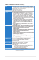
F2A85-V PRO specifications summary APU Chipset Memory Graphics Expansion slots Multi-GPU support Storage / RAID LAN FM2 socket for AMD® A-Series Accelerated Processor Unit (APU) with AMD Radeon™ HD 7000 Series Graphics, up to 4 CPU cores Supports AMD® Turbo Core Technology 3.0 Supports Microsoft® DirectX® 11 AMD® A85X FCH (Hudson-D4) Dual-channel memory architecture 4 x 240-pin DIMM slots support maximum 64GB unbuffered nonECC DDR3 2400(O.C.) / 2250(O.C.) / 2200(O.C.) / 2133(O.C.) / 2000(O.C.
F2A85-V PRO specifications summary Audio USB ASUS unique features ALC892 supports 8-channel High Definition Audio - Optical S/PDIF Out port at the back I/O - Supports Jack-detection, Multi-streaming, and Front Panel Jack-Retasking Asmedia® USB3.0 controller - 2 x USB 3.0/2.0 ports (blue, at the back panel) AMD® A85X FCH - 4 x USB 3.0/2.0 ports (2 ports at the back panel [blue], 2 ports at the mid-board) - 10 x USB 2.0/1.
F2A85-V PRO specifications summary ASUS unique features ASUS EZ DIY - ASUS UEFI BIOS EZ Mode featuring friendly graphics user interface - ASUS USB BIOS Flashback with USB BIOS Flashback Wizard for EZ BIOS download scheduling - DirectKey - ASUS CrashFree BIOS 3 - ASUS MyLogo 2 - ASUS EZ Flash 2 ASUS exclusive Precision Tweaker 2 overclocking - vCore: Adjustable CPU voltage at 0.00625V increment features - vDDNB: Adjustable CPU/NB voltage at 0.00625V increment - vDRAM Bus: Adjustable DRAM voltage at 0.
F2A85-V PRO specifications summary BIOS features 64Mb Flash ROM, UEFI BIOS, PnP, DMI v2.0, WfM 2.0, ACPI v3.0, SM BIOS 2.7, Multi-language BIOS, ASUS EZ Flash 2, ASUS CrashFree BIOS 3, F12 PrintScreen Function, F3 Shortcut Function and ASUS DRAM SPD (Serial Presence Detect) Memory information Support DVD contents Drivers ASUS Update ASUS utilities Anti-Virus software (OEM version) Accessories 4 x Serial ATA 6.
Chapter 1 Chapter 1: Product introduction 1.1 Welcome! Thank you for buying an ASUS® F2A85-V PRO motherboard! Chapter 1 The motherboard delivers a host of new features and latest technologies, making it another standout in the long line of ASUS quality motherboards! Before you start installing the motherboard, and hardware devices on it, check the items in your package with the list below. 1.2 Package contents Check your motherboard package for the following items.
1.3 Special features 1.3.1 Product highlights Chapter 1 AMD® A-series accelerated processors with AMD® Radeon™ HD 7000 series graphics This motherboard supports AMD® A-series accelerated processor with AMD® Radeon™ HD 7000 series graphics. This revolutionary APU (Accelerated Processing Unit) combines processing power and advanced DirectX 11 graphics in one small, energy-efficient design to enable accelerated performance and an industry-leading visual experience.
New DIGI+ Power Control All-New Digital Power Control for both APU and DRAM Chapter 1 The New DIGI+ Power Control design with two digital voltage controllers upgrades motherboard power delivery to an overall solution on AMD FM2 motherboards, including allnew DRAM controllers that offers ultra-precise memory tuning in addition to ultra-precise APU voltage control.
Auto Tuning Auto Tuning is an intelligent tool that automates overclocking to achieve a total system level up. This tool also provides stability testing. Even O.C. beginners can achieve extreme yet stable overclocking results with Auto Tuning! Chapter 1 GPU Boost Go to the Limit with iGPU Level Up! GPU Boost accelerates the integrated GPU for extreme graphics performance. The userfriendly interface facilitates flexible frequency adjustments. It easily delivers stable systemlevel upgrades for every use.
AI Suite II One-stop Access to Innovative ASUS Features Chapter 1 With its user-friendly interface, ASUS AI Suite II consolidates all the exclusive ASUS features into one simple to use software package. It allows you to supervise overclocking, energy management, fan speed control, voltage and sensor readings. This all-in-one software offers diverse and ease to use functions, with no need to switch back and forth between different utilities.
1.3.5 ASUS EZ DIY ASUS UEFI BIOS Flexible and Easy BIOS Interface Chapter 1 ASUS UEFI BIOS offers the first mouse-controlled graphical BIOS designed with selectable modes, providing a user-friendly interface that goes beyond the traditional keyboard-only controls. It also natively supports fully-utilized hard drives larger than 2.2TB in 64-bit operating systems. ASUS exclusive interface EZ Mode displays frequently-accessed info.
CrashFree BIOS 3 Simply restore corrupted BIOS data from USB flash disk Chapter 1 The ASUS CrashFree BIOS 3 allows users to restore corrupted BIOS data from a USB flash disk containing the BIOS file. This utility saves users the cost and hassle of buying a replacement BIOS chip. ASUS Q-Design ASUS Q-Design enhances your DIY experience.
Chapter 1 1-8 Chapter 1: Product Introduction
Chapter 2 Chapter 2: Hardware information 2.1 Before you proceed Take note of the following precautions before you install motherboard components or change any motherboard settings. • Unplug the power cord from the wall socket before touching any component. • Before handling components, use a grounded wrist strap or touch a safely grounded object or a metal object, such as the power supply case, to avoid damaging them due to static electricity.
2.2 Motherboard overview 2.2.1 Motherboard layout 1 2 2 3 4 5 24.4cm(9.6in) EPU CPU_FAN CHA_FAN3 KBMS_USB12 EPU_LED DIGI+ 6 DIGI+ EPU SPDIFO _HDMI _DP EATX12V 7 MemOK! EATXPWR 1 30.5cm(12.
Connectors/Jumpers/Slots Page 1. ATX power connectors (24-pin EATXPWR, 8-pin EATX12V) 2-26 2. CPU and chassis fan connectors (4-pin CPU_FAN, 4-pin CHA_FAN1/2/3/4) 2-24 3. AMD FM2 Socket 2-4 4. EPU switch 2-17 5. EPU LED (EPU_LED) 2-21 6. DDR3 DIMM slots 2-5 7. DRAM LED (DRAM_LED) 2-20 8. MemOK! switch 2-16 9. USB 3.0 connector (20-1 pin USB3_34) 2-25 10. SATA 6.0 Gb/s connectors (SATA6G_1~7) 2-22 11. BIOS Flashback button (BIOS_FLBK) 2-19 12.
2.2.2 Accelerated Processing Unit (APU) This motherboard comes with an FM2 socket designed for AMD™ A-Series Accelerated processors. Ensure that you use a APU designed for the FM2 socket. The APU fits in only one correct orientation.
2.2.3 System memory The motherboard comes with four Double Data Rate 3 (DDR3) Dual Inline Memory Modules (DIMM) sockets. DIMM_B1 DIMM_B2 DIMM_A1 DIMM_A2 A DDR3 module is notched differently from a DDR or DDR2 module. DO NOT install a DDR or DDR2 memory module to the DDR3 slot. Chapter 2 F2A85-V PRO F2A85-V PRO 240-pin DDR3 DIMM sockets Recommended memory configurations We recommend that you install the memory modules from the blue slots for better overclocking capability.
Memory configurations You may install 1GB, 2GB, 4GB and 8GB unbuffered non‑ECC DDR3 DIMMs into the DIMM sockets. • You may install varying memory sizes in Channel A and Channel B. The system maps the total size of the lower-sized channel for the dual-channel configuration. Any excess memory from the higher-sized channel is then mapped for single-channel operation. • We recommend that you install the memory modules from the blue slots for better overclocking capability.
DDR3 2200 (O.C.) MHz capability DIMM socket support (Optional) Vendors Part No. Size SS/DS Chip Brand Chip NO. Timing Voltage GEIL GEIL Kingmax Kingmax GET34GB2200C9DC(XMP) GET38GB2200C9ADC(XMP) FLKE85F-B8KJAA-FEIS(XMP) FLKE85F-B8KHA EEIH(XMP) 2GB 4GB 2GB 4GB(2 x 2GB) DS DS DS DS - 1.65V 1.65V 1.5V-1.7V Kingmax FLKE85F-B8KJA FEIH(XMP) - 4GB(2 x 2GB) DS - 9-10-9-28 9-11-9-28 - - - 1 DIMM 2 DIMMs 4 DIMMs 1.5V-1.7V ● ● ● ● ● ● ● ● ● ● ● ● ● DDR3 2133 (O.C.
DDR3 1600 MHz capability Vendors Part No. Size SS/ DS Chip Brand Chip NO. A-DATA AM2U16BC2P1 2GB SS ADATA 3CCD-1509A EL1126T A-DATA AX3U1600XB2G79-2X(XMP) 4GB(2 x 2GB) DS - - 3CCD-1509A EL1126T Timing Voltage DIMM socket support (Optional) 1 DIMM 2 DIMMs 4 DIMMs Chapter 2 - ● 1.55V1.75V ● - ● ● ● ● ● ● ● ● ● ● ● ● ● ● 1.50V ● ● 1.65V 1.65V 1.65V 1.65V 1.65V 1.65V 1.65V 1.65V 1.65V 1.50V 1.65V 1.5V 1.6V XMP 1.35V 1.6V 1.60V XMP 1.35V 1.5V 1.5V~1.6V 1.6V XMP 1.35V 1.
DDR3 1600 MHz capability Part No. Transcend JM1600KLN-8GK DIMM socket support (Optional) Size SS/ DS Chip Brand Chip NO. Timing Voltage 8GB(4GB x 2) DS Transcend - - - - ● ● 9-9-9-24 1.5V ● ● 9-9-9-24 1.5V ● ● - - ● ● ● 9-9-9-24 - 1.6V - ● ● ● ● ● ● ● ● - - ● ● ● - - ● ● - - ● ● ● - - ● ● ● 9-9-9-24 9-9-9-24 9-9-9-24 7-7-7-20 1.5~1.6V 1.65V 1.
DDR3 1333 MHz capability Vendors Part No. Size SS/ Chip DS Brand Chip NO. Timing Crucial Crucial 2GB 6GB(3 x 2GB) DS Micron DS - 9KF27D9KPT - 9 7-7-7-24 1.65V ELPIDA CT25664BA1339.16FF BL25664BN1337.16FF (XMP) EBJ10UE8EDF0-DJ-F 1GB SS ELPIDA J1108EDSE-DJ-F - ELPIDA EBJ21UE8EDF0-DJ-F 2GB DS ELPIDA J1108EDSE-DJ-F - G.SKILL 1GB SS - - 2GB(2 x 1GB) 4GB(2 x 2GB) SS DS - - 8GB(2 x 4GB) DS - - 9-9-9-24 1.5V 8-8-8-24 XMP 1.35V 7-7-7-21 1.
DDR3 1333 MHz capability Part No. Size SS/ Chip Brand Chip NO.
DDR3 1066 MHz capability Vendors Part No. Size SS/DS Chip Brand Chip NO. Timing Voltage Crucial Crucial ELPIDA CT12864BA1067.8FF CT25664BA1067.16FF EBJ10UE8EDF0-AE-F 1GB 2GB 1GB SS DS SS Micron Micron ELPIDA 9GF22D9KPT 9HF22D9KPT J1108EDSE-DJ-F 7 7 - ELPIDA EBJ21UE8EDF0-AE-F 2GB DS ELPIDA J1108EDSE-DJ-F - Kingston Kingston Kingston KVR1066D3N7/1G(low profile) KVR1066D3N7/2G KVR1066D3N7/4G 1GB 2GB 4GB SS DS DS ELPIDA ELPIDA Hynix J1108BFSE-DJ-F J1108BDSE-DJ-F H5TQ2G83AFR 7 7 7 1.
2.2.4 Expansion slots Chapter 2 Ensure to unplug the power cord before adding or removing expansion cards. Failure to do so may cause you physical injury and damage motherboard components. 1 2 F2A85-V PRO 3 4 5 6 7 Slot No. Slot Description 1 PCIe 2.0 x1_1 slot 2 PCIe 2.0 x16_1 slot [navy blue] (single at x16 or dual at x8/x8 mode) 3 PCIe 2.0 x1_2 slot 4 PCI slot 1 5 PCIe 2.0 x16_2 slot [gray] (at x8 mode) 6. PCI slot 2 7. PCIe 2.
• In single VGA card mode, use the PCIe 2.0 x16_1 slot (navy blue) for a PCI Express x16 graphics card to get better performance. • In CrossFireX™ mode, use the PCIe 2.0 x16_1 and PCIe 2.0 x16_2 slots for PCI Express x16 graphics cards to get better performance. • We recommend that you provide sufficient power when running CrossFireX™ mode. Refer to page 2-26 for details.
2.2.5 Jumper Clear RTC RAM (3-pin CLRTC) This jumper allows you to clear the Real Time Clock (RTC) RAM in CMOS. You can clear the CMOS memory of date, time, and system setup parameters by erasing the CMOS RTC RAM data. The onboard button cell battery powers the RAM data in CMOS, which include system setup information such as system passwords. CLRTC 1 2 2 3 Normal (Default) Clear RTC Chapter 2 F2A85-V PRO F2A85-V PRO Clear RTC RAM To erase the RTC RAM 1. 2. 3. 4.
2.2.6 Onboard switches Onboard switches allow you to fine-tune performance when working on a bare or open-case system. This is ideal for overclockers and gamers who continually change settings to enhance system performance. 1. MemOK! switch Installing DIMMs that are incompatible with the motherboard may cause system boot failure, and the DRAM_LED near the MemOK! switch lights continuously.
2. TPU (GPU Boost) switch Turning this switch to Enable will automatically optimize the system for fast, yet stable clock speeds. TPU F2A85-V PRO F2A85-V PRO TPU switch Chapter 2 • To ensure system performance, turn the switch setting to Enable when the system is powered off. • When the TPU switch is set to Enable, it can be used as a GPU Boost switch. • The TPU LED near the TPU switch lights when the switch setting is turned to Enable. Refer to section 2.2.
• The EPU LED near the TPU switch lights when the switch setting is turned to Enable. • If you change the switch setting to Enable under the OS environment, the EPU function will be activated after the next system bootup. • You may change the EPU settings in the EPU application, change the BIOS settings, and enable the EPU function at the same time. However, the system will use the last setting you have made. 4.
5. BIOS-FLBK switch The BIOS Flashback buttton offers the most convenient way to update the BIOS. It allows overclockers to update new BIOS versions without having to enter their existing BIOS or operating system. Just plug in a USB storage and press the BIOS Flashback button for 3 seconds, and the BIOS is automatically flashed using standby power. Hassle-free updating for the ultimate convenience! F2A85-V PRO Chapter 2 BIOS_FLBK F2A85-V PRO BIOS Flashback switch 1. 2. 3. 4. 5. 6.
2.2.7 1. Onboard LEDs Standby Power LED The motherboard comes with a standby power LED. The green LED lights up to indicate that the system is ON, in sleep mode, or in soft‑off mode. This is a reminder that you should shut down the system and unplug the power cable before removing or plugging in any motherboard component. The illustration below shows the location of the onboard LED. SB_PWR F2A85-V PRO Chapter 2 ON Standby Power OFF Powered Off F2A85-V PRO Onboard LED 2.
3. BIOS_FLBK LED The BIOS_FLBK LED lights when the BIOS-FLBK function is enabled. F2A85-V PRO FLBK_LED 4. Chapter 2 F2A85-V PRO BIOS Flashback LED EPU LED The EPU LED lights when the EPU switch is turned to Enable. EPU_LED F2A85-V PRO F2A85-V PRO EPU LED 5. TPU LED The TPU LED lights when the TPU switch is turned to Enable.
2.2.8 1. Internal connectors Serial ATA 6.0 Gb/s connectors (7-pin SATA6G_1~7) These connectors connect to Serial ATA 6.0 Gb/s hard disk drives via Serial ATA 6.0 Gb/s signal cables. If you installed Serial ATA hard disk drives, you can create a RAID 0, 1, 5, and 10 configuration through the onboard AMD® A85X chipset.
USB 2.0 connectors (10-1 pin USB 3 ~ 10) These connectors are for USB 2.0 ports. Connect the USB module cable to any of these connectors, then install the module to a slot opening at the back of the system chassis. These USB connectors comply with USB 2.0 specification that supports up to 480 Mbps connection speed. USB+5V USB_P8USB_P8+ GND NC USB56 USB34 USB+5V USB_P4USB_P4+ GND NC USB78 USB+5V USB_P10USB_P10+ GND NC USB910 USB+5V USB_P6USB_P6+ GND NC 2.
Digital audio connector (4-1 pin SPDIF_OUT) This connector is for an additional Sony/Philips Digital Interface (S/PDIF) port. Connect the S/PDIF Out module cable to this connector, then install the module to a slot opening at the back of the system chassis. +5V F2A85-V PRO SPDIFOUT GND 4. SPDIF_OUT F2A85-V PRO Digital audio connector Chapter 2 The S/PDIF module is purchased separately.
6. USB 3.0 connector (20-1 pin USB3_34) These connectors are for the additional USB 3.0 ports, and complies with the USB 3.0 specificaton that supports up to 4.8Gbps connection speed. If the USB 3.0 front panel cable is available from your system chassis, with this USB 3.0 connector, you can have a front panel USB 3.0 solution. USB3_34 F2A85-V PRO Chapter 2 F2A85-V PRO USB3.0 Front panel connector You can connect the ASUS front panel USB 3.0 bracket to this connector to obtain the front panel USB 3.
8. ATX power connectors (24-pin EATXPWR; 8-pin EATX12V) These connectors are for ATX power supply plugs. The power supply plugs are designed to fit these connectors in only one orientation. Find the proper orientation and push down firmly until the connectors completely fit.
10. System panel connector (20-8 pin PANEL) This connector supports several chassis-mounted functions. +5V Ground Ground Speaker SPEAKER PLED- PLED+ PLED PANEL F2A85-V PRO IDE_LED PWRSW Reset Ground IDE_LED+ IDE_LED- PWR Ground PIN 1 RESET * Requires an ATX power supply F2A85-V PRO System panel connector • • • • System power LED (2-pin PLED) Chapter 2 • This 2-pin connector is for the system power LED. Connect the chassis power LED cable to this connector.
2.3 Building your computer system 2.3.1 Additional tools and components to build a PC system Chapter 2 1 bag of screws Philips (cross) screwdriver PC chassis Power supply unit AMD FM2 APU AMD FM2 compatible CPU Fan DIMM SATA hard disk drive SATA optical disc drive (optional) Graphics card (optional) The tools and components in the table above are not included in the motherboard package.
2.3.2 APU installation Ensure that you use a APU designed for the FM2 socket. The APU fits in only one correct orientation.
2.3.3 APU heatsink and fan assembly installation Apply the Thermal Interface Material to the APU heatsink and APU before you install the heatsink and fan if necessary.
To uninstall the APU heatsink and fan assembly 3 2 Chapter 2 1 4 5 ASUS F2A85-V PRO 2-31
2.3.
2.3.5 Motherboard installation The diagrams in this section are for reference only. The motherboard layout may vary with models, but the installation steps remain the same.
3 Chapter 2 F2A85-V PRO DO NOT overtighten the screws! Doing so can damage the motherboard.
2.3.
2.3.
2.3.8 Front I/O Connector To install ASUS Q-Connector 1 2 PWR Ground IDE_LED POWE Reset Ground R SW RESET SW To install USB 2.0 Connector Chapter 2 IDE_LED+ IDE_LED- To install front panel audio connector AAFP USB 2.0 To install USB 3.0 Connector USB 3.
2.3.
2.3.10 Rear panel connection Chapter 2 12 Rear panel connectors 1. PS/2 keyboard/mouse combo port 2. Optical S/PDIF Out port 3. 7. ASMedia USB 3.0 ports 1 and 2, support ASUS USB 3.0 Boost UASP Mode 8. AMD USB 3.0 ports 1 and 2, support ASUS USB 3.0 Boost UASP Mode. Bottom port supports USB BIOS Flashback and USB Charger+ Video Graphics Adapter (VGA) port 9. DVI-D port 4. External SATA 6.0Gb/s port 10. HDMI port 5. ® Realtek LAN (RJ-45) port* 11. DisplayPort 6.
* LAN port LED indications ACT/LINK SPEED LED LED Activity Link LED Speed LED Status Description Status Description OFF No link OFF 10 Mbps connection ORANGE Linked ORANGE 100 Mbps connection BLINKING Data activity GREEN 1 Gbps connection LAN port ** Audio 2, 4, 6, or 8-channel configuration Port Headset 2-channel 4-channel 6-channel 8-channel Light Blue Line In Line In Line In Line In Lime Line Out Front Speaker Out Front Speaker Out Front Speaker Out Chapter 2 Pink Mic
2.3.11 Audio I/O connections Audio I/O ports Chapter 2 Connect to Headphone and Mic Connect to Stereo Speakers Connect to 2.
Connect to 4.1 channel Speakers Connect to 5.1 channel Speakers Chapter 2 Connect to 7.
2.4 Starting up for the first time 1. After making all the connections, replace the system case cover. 3. Connect the power cord to the power connector at the back of the system chassis. 4. 5. Be sure that all switches are off. Connect the power cord to a power outlet that is equipped with a surge protector. Turn on the devices in the following order: a. Monitor c. System power b. 6.
Chapter 2 2-44 Chapter 2: Hardware information
Chapter 3 Chapter 3: 3.1 Knowing BIOS BIOS setup The ASUS UEFI BIOS offers a user-friendly interface that goes beyond traditional keyboard-only BIOS controls to enable more flexible and convenient mouse input. Users can easily navigate the UEFI BIOS with the same smoothness as their operating system. The term “BIOS” in this user manual refers to “UEFI BIOS” unless otherwise specified.
3.2.1 EZ Mode By default, the EZ Mode screen appears when you enter the BIOS setup program. The EZ Mode provides you an overview of the basic system information, and allows you to select the display language, system performance mode and boot device priority. To access the Advanced Mode, click Exit/Advanced Mode, then select Advanced Mode or press F7 hot key for the advanced BIOS settings�. The default screen for entering the BIOS setup program can be changed.
3.2.2 Advanced Mode The Advanced Mode provides advanced options for experienced end-users to configure the BIOS settings. The figure below shows an example of the Advanced Mode. Refer to the following sections for the detailed configurations. To access the Advanced Mode, click Exit, then select Advanced Mode.
Menu items The highlighted item on the menu bar displays the specific items for that menu. For example, selecting Main shows the Main menu items. The other items (Ai Tweaker, Advanced, Monitor, Boot, Tool, and Exit) on the menu bar have their respective menu items. Back button This button appears when entering a submenu. Press or use the USB mouse to click this button to return to the previous menu screen.
3.3 Main menu The Main menu screen appears when you enter the Advanced Mode of the BIOS Setup program. The Main menu provides you an overview of the basic system information, and allows you to set the system date, time, language, and security settings.
Administrator Password If you have set an administrator password, we recommend that you enter the administrator password for accessing the system. Otherwise, you might be able to see or change only selected fields in the BIOS setup program. To set an administrator password: 1. Select the Administrator Password item and press . 3. Confirm the password when prompted. 2. From the Create New Password box, key in a password, then press . To change an administrator password: 1. 2. 3. 4.
3.4 Ai Tweaker menu The Ai Tweaker menu items allow you to configure overclocking-related items. Be cautious when changing the settings of the Ai Tweaker menu items. Incorrect field values can cause the system to malfunction. The configuration options for this section vary depending on the CPU and DIMM model you installed on the motherboard.
Ai Overclock Tuner [Auto] Allows you to select the CPU overclocking options to achieve the desired CPU internal frequency. Select any of these preset overclocking configuration options: [Auto] [Manual] Loads the optimal settings for the system. Allows you to individually set overclocking parameters. The following item appears only when you set the Ai Overclocking Tuner item to [Manual]. APU Frequency [XXX] Allows you to adjust the APU frequency to enhance the system performance.
The following item appears only when you set the GPU Boost item to [Manual Mode]. GPU Engine Frequency [Auto] Allows you to set the GPU Engine Frequency. Configuration options: [Auto] [GPU O.C. 434MHz] [GPU O.C. 447MHz] [GPU O.C. 460MHz] [GPU O.C. 475MHz] ~ [GPU O.C. 1381MHz] [GPU O.C. 1520MHz] [GPU O.C. 1688MHz] [GPU O.C. 1900MHz] OC Tuner OC Tuner automatically overclocks the frequency and voltage of CPU and DRAM for enhancing the system performance.
CPU Power Phase Control [Standard] Phase number is the number of working VRM phase. Increase the phase number under heavy system loading to get more transient and better thermal performance. Reduce the phase number under light system loading to increase VRM efficiency. [Standard] [Optimized] [Extreme] [Manual Adjustment] Proceeds to phase control depending on the CPU loading. Loads the ASUS optimized phase tuning profile. Proceeds to the full phase mode. Allows manual adjustment.
DRAM Fixed Frequency Mode [300] This item only appears when you set the DRAM Frequency Mode item to [Manual], and allows you to set a fixed DRAM frequency. Use the <+> and <-> keys to adjust the value. The values range from 300k Hz to 500k Hz with a 50k Hz interval. DRAM Power Phase Control [Auto] [Auto] Allows you to set the Auto mode. [Optimized] Allows you to set the ASUS optimized phase tuning profile. [Extreme] Allows you to set the full phase mode.
VDDNB Manual Voltage [Auto] This item appears only when you set the CPU Voltage item to [Manual Mode] and allows you to set a fixed VDDNB voltage. The values range from 0.800V to 1.750V with a 0.00625V interval. DRAM Voltage [Auto] Allows you to set the DRAM voltage. The values range from 1.35V to 2.135V with a 0.005V interval. SB 1.1V Voltage [Auto] Allows you to set the Southbridge 1.1V voltage. The values range from 1.1V to 1.4V with a 0.01V interval. 1.1VSB Voltage [Auto] Allows you to set the 1.
3.5 Advanced menu The Advanced menu items allow you to change the settings for the CPU and other system devices. Be cautious when changing the settings of the Advanced menu items. Incorrect field values can cause the system to malfunction.
3.5.1 CPU Configuration The items in this menu show the CPU-related information that the BIOS automatically detects. The items shown in this screen may be different due to the CPU you installed. UEFI BIOS Utility - Advanced Mode Ai Tweaker Main Back Advanced Exit Monitor Boot Tool Advanced\ CPU Configuration > CPU Configuration Enable/disable PowerNow function.
IOMMU [Disabled] Set this item to [Enabled] to show IOMMU Mode. Configuration options: [Enabled] [Disabled] 3.5.2 SATA Configuration While entering Setup, the BIOS automatically detects the presence of SATA devices. The SATA Port items show Not Present if no SATA device is installed to the corresponding SATA port.
SATA Port 5, 6, 7, ESATA [RAID] This item only appears when OnChip SATA Type is set to [RAID]. If SATA ports 5, 6, 7, and the eSATA port are configured as [RAID], the ports can only be used under OS with driver installed. Set to [IDE] instead of [RAID] to access devices on SATA ports 5, 6, 7, and the eSATA port before entering OS. Configuration options: [RAID] [IDE] Board SATA RAID ROM [Legacy ROM] This item only appears when the OnChip SATA Type item is set to [RAID]. [Disabled] Disables this function.
Legacy USB3.0 Support [Enabled] [Enabled] Enables the support for USB 3.0 devices on legacy operating systems (OS). Disables the function. [Disabled] EHCI Hand-off [Disabled] [Enabled] Enables the support for operating systems without an EHCI hand‑off feature. Disables the function. [Disabled] 3.5.
PCIex16_1 [Auto] Sets the speed mode for the PCIex16_1 slot. When [Force X16] is selected, the PCIex16_1 slot will be disabled. Configuration options: [Auto] [Force X16] [Force X8] 3.5.
Realtek LAN Controller [Enabled] [Enabled] [Disabled] Enables the Realtek LAN controller. Disables the controller. Realtek PXE OPROM [Disabled] This item appears only when you set the previous item to [Enabled] and allows you to enable or disable the PXE OptionRom of the Realtek LAN controller. Configuration options: [Enabled] [Disabled] Asmedia USB 3.0 Controller [Enabled] [Enabled] [Disabled] Enables the USB 3.0 controller. Disables the controller. Asmedia USB 3.
Restore AC Power Loss [Power Off] [Power On] [Power Off] [Last State] The system goes into on state after an AC power loss. The system goes into off state after an AC power loss. The system goes into either off or on state, whatever the system state was before the AC power loss. Power On By PS/2 Keyboard [Disabled] [Disabled] [Space Bar] [Ctrl-Esc] [Power Key] Disables the Power On by a PS/2 keyboard. Sets the Space Bar on the PS/2 keyboard to turn on the system.
3.5.7 Network Stack UEFI BIOS Utility - Advanced Mode Main Back Ai Tweaker Advanced Exit Monitor Boot Tool Advanced\ Network Stack > Network Stack Disable Link Enable/Disable UEFI network stack Network Stack [Disable Link] Enables or disables the UEFI network stack. Configuration options: [Disable Link] [Enabled] Ipv4 PXE Support [Enabled] This item appears only when you set the Network Stack item to [Enabled]. When this item is disabled, the IPV4 PXE boot option will not be created.
3.6 Monitor menu The Monitor menu displays the system temperature/power status, and allows you to change the fan settings. UEFI BIOS Utility - Advanced Mode Main Ai Tweaker Exit Advanced Monitor Boot Tool CPU Temperature �������������� +73ºC / +163ºF MB Temperature CPU_FAN Speed +31ºC / +87ºF 4192 RPM CHA_FAN1 Speed N/A CHA_FAN2 Speed N/A CHA_FAN3 Speed N/A CHA_FAN4 Speed N/A CPU Voltage +1.186 V 3.3V Voltage +3.312 V 5V Voltage +5.080 V 12V Voltage +12.
CPU Temperature / MB Temperature ������������� [xxxºC/xxxºF] The onboard hardware monitor automatically detects and displays the CPU and motherboard temperatures. Select Ignore if you do not wish to display the detected temperatures. CPU_FAN Speed [xxxx RPM] or [Ignore] / [N/A] CHA_FAN1/2/3/4 Speed [xxxx RPM] or [Ignore] / [N/A] The onboard hardware monitor automatically detects and displays the CPU and chassis fan speeds in rotations per minute (RPM).
CPU_FAN���������������������������� Fan Min. Duty Cycle(%) [20] Use the <+> and <-> keys to adjust the minimum CPU fan duty cycle. The values range from 0% to 100%. When the CPU temperature is under 40ºC, the CPU fan will operate at the minimum duty cycle. CHA_FAN1/2/3/4 Q-Fan Control [Enabled] [Disabled] [Enabled] Disables the Chassis Q-Fan control feature. Enables the Chassis Q-Fan control feature.
3.7 Boot menu The Boot menu items allow you to change the system boot options. UEFI BIOS Utility - Advanced Mode Ai Tweaker Main Exit Advanced Monitor Bootup NumLock State On Full Screen Logo Enabled Fast Boot Enabled USB Support Partial In... PS2 Devices Support Enabled Network Stack Driver Support Disabled Post Logo Delay Time Wait for ‘F1’ If Error Tool Select the keyboard NumLock state 3 sec Enabled DirectKey Enable Go to BIOS...
Fast Boot [Enabled] Enable or disable boot with initialization of a minimal set of devices to launch active boot option. Configuration options: [Disabled] [Enabled] The following three items appear only when you set Fast Boot to [Enabled]. USB Support [Partial Initial] [Disabled] All USB devices will not be available until OS bootup for a fastest POST time. [Full Initial] All USB devices will be available during POST. This process will extend the POST time.
Option ROM Messages [Force BIOS] [Force BIOS] [Keep Current] The third-party ROM messages will be forced to display during the boot sequence. The third-party ROM messages will be displayed only if the third-party manufacturer had set the add-on device to do so. Next boot after AC Power Loss [Normal Boot] [Normal Boot] [Fast Boot] Returns to normal boot on the next boot after an AC power loss. Accelerates the boot speed on the next boot after an AC power loss.
Removable Media [Deny Execute] Configuration options: [Always Execute] [Always Deny] [Allow Execute] [Defer Execute] [Deny Execute] [Query Execute] Fix Media [Deny Execute] Configuration options: [Always Execute] [Always Deny] [Allow Execute] [Defer Execute] [Deny Execute] [Query Execute] Key Management Default Key Provisioning [Disabled] Configuration options: [Enabled] [Disabled] Manage All Factory Keys (PK, KEK, DB, DBX) Install default Secure Boot Keys Configuration options: [Yes] [No] Platform Key
Forbidden Signature Database Set DBX from File Configuration options: [OK] Get DBX to File Configuration options: [OK] Delete the DBX Configuration options: [Yes] [No] Append an entry to DBX Configuration options: [OK] Setup Mode [EZ Mode] [Advanced Mode] Sets Advanced Mode as the default screen for entering the BIOS setup program. [EZ Mode] Sets EZ Mode as the default screen for entering the BIOS setup program.
3.8 Tools menu The Tools menu items allow you to configure options for special functions. Select an item then press to display the submenu. UEFI BIOS Utility - Advanced Mode Ai Tweaker Main Advanced Exit Monitor Boot Tool Be used to update BIOS > ASUS EZ Flash 2 Utility > ASUS SPD Information > ASUS O.C. Profile ASUS EZ Flash 2 Utility Allows you to run ASUS EZ Flash 2. Press [Enter] to launch the ASUS EZ Flash 2 screen. For more details, refer to section 3.10.2 ASUS EZ Flash 2 utility.
ASUS O.C. Profile This item allows you to store or load multiple BIOS settings. UEFI BIOS Utility - Advanced Mode Ai Tweaker Main Back Exit Advanced Monitor O.C. Profile Configuration Setup Setup Setup Setup Setup Setup Setup Setup Profile Profile Profile Profile Profile Profile Profile Profile Boot Tool Tool\ ASUS O.C.
3.9 Exit menu The Exit menu items allow you to load the optimal default values for the BIOS items, and save or discard your changes to the BIOS items. You can access the EZ Mode from the Exit menu. Exit Load Optimized Defaults Save Changes & Reset Discard Changes & Exit ASUS EZ Mode Launch EFI Shell from filesystem device Load Optimized Defaults This option allows you to load the default values for each of the parameters on the Setup menus.
3.10 Updating BIOS The ASUS website publishes the latest BIOS versions to provide enhancements on system stability, compatibility, or performance. However, BIOS updating is potentially risky. If there is no problem using the current version of BIOS, DO NOT manually update the BIOS. Inappropriate BIOS updating may result in the system’s failure to boot. Carefully follow the instructions of this chapter to update your BIOS if necessary. Visit the ASUS website (www.asus.
Updating the BIOS through the Internet To update the BIOS through the Internet: 1. From the ASUS Update screen, select Update BIOS from Internet, and then click Next. 2. Select the ASUS FTP site nearest you to avoid network traffic. If you want to enable the BIOS downgradable function and auto BIOS backup function, check the checkboxs before the two items on the screen. Select the BIOS version that you want to download. Click Next. 4.
Updating the BIOS through a BIOS file 1. From the ASUS Update screen, select Update BIOS from file, and then click Next. 2. Locate the BIOS file from the Open window, click Open, and click Next. 3. You can decide whether to change the BIOS boot logo. Click Yes if you want to change the boot logo or No to continue. 4. Chapter 3 To update the BIOS through a BIOS file: Follow the onscreen instructions to complete the update process. • The screenshots in this section are for reference only.
3.10.2 ASUS EZ Flash 2 utility The ASUS EZ Flash 2 feature allows you to update the BIOS without having to use a bootable floppy disk or an OS‑based utility. Before you start using this utility, download the latest BIOS from the ASUS website at www.asus.com. To update the BIOS using EZ Flash 2: 1. Insert the USB flash disk that contains the latest BIOS file to the USB port. 2. ������������������������������������������������������������� Enter the Advanced Mode of the BIOS setup program.
• This function can support devices such as a USB flash disk with FAT 32/16 format and single partition only. • DO NOT shut down or reset the system while updating the BIOS to prevent system boot failure! Ensure to load the BIOS default settings to ensure system compatibility and stability. Select the Load Optimized Defaults item under the Exit menu. See section 3.9 Exit Menu for details. 3.10.
3.10.4 ASUS BIOS Updater The ASUS BIOS Updater allows you to update BIOS in DOS environment. This utility also allows you to copy the current BIOS file that you can use as a backup when the BIOS fails or gets corrupted during the updating process. The succeeding utility screens are for reference only. The actual utility screen displays may not be same as shown. Before updating BIOS 1. 2. Prepare the motherboard support DVD and a USB flash drive in FAT32/16 format and single partition.
Updating the BIOS file To update the BIOS file using BIOS Updater 1. At the FreeDOS prompt, type bupdater /pc /g and press . D:\>bupdater /pc /g 2. The BIOS Updater screen appears as below. ASUSTek BIOS Updater for DOS V1.30 Current ROM BOARD: F2A85-V PRO VER: 0301 DATE: 04/26/2012 Update ROM BOARD: Unknown VER: Unknown DATE: Unknown PATH: A:\ F2A85VP.
Chapter 3 3-40 Chapter 3: BIOS setup
Chapter 4 Chapter 4: 4.1 Software support Installing an operating system This motherboard supports Windows® XP / Vista / 64-bit Vista / Windows® 7 / 64-bit Windows® 7 / Windows® 8 / 64-bit Windows® 8 operating systems (OS). Always install the latest OS version and corresponding updates to maximize the features of your hardware. • Motherboard settings and hardware options vary. Use the setup procedures presented in this chapter for reference only. Refer to your OS documentation for detailed information.
4.2.2 Obtaining the software manuals The software manuals are included in the support DVD. Follow the instructions below to get the necessary software manuals. The software manual files are in Portable Document Format (PDF). Install the Adobe® Acrobat® Reader from the Utilities menu before opening the files. 1. Click the Manual tab. Click ASUS Motherboard Utility Guide from the manual list on the left. 2. The Manual folder of the support DVD appears. Double-click the folder of your selected software.
4.3 Software information Most of the applications in the support DVD have wizards that will conveniently guide you through the installation. View the online help or readme file that came with the software application for more information. 4.3.1 AI Suite II AI Suite II is an all-in-one interface that integrates several ASUS utilities and allows users to launch and operate these utilities simultaneously. Installing AI Suite II To install AI Suite II on your computer 1. 2. 3.
4.3.2 TurboV EVO ASUS TurboV EVO introduces TurboV that allows you to manually adjust the APU frequency and related voltages as well as Auto Tuning function that offers automatic and easy overlocking and system level up. After installing AI Suite II from the motherboard support DVD, launch TurboV EVO by clicking Tool > TurboV EVO on the AI Suite II main menu bar. Refer to the software manual in the support DVD or visit the ASUS website at www.asus.com for detailed software configuration.
Using Advanced Mode Click on the Advanced Mode tab to adjust the advanced voltage settings. Advanced mode Voltage Adjustment bars Target values Current values Undoes all changes without applying Applies all changes immediately Click to restore all start-up settings GPU Boost GPU Boost overclocks the integrated iGPU for the best graphics performance. 1. Click on the GPU Boost tab. 3. Click Apply to make the change takes effect. 2. Adjust the GPU Boost settings.
APU Multiplier Allows you to manually adjust the APU Multiplier. 1. Click on the APU Multiplier tab. 3. Click on Apply to make the change take effect. 2. Drag the adjustment bar leftwards or rightwards to the desired value. APU Multiplier Adjustment bar Undoes all changes without applying Click to restore all start-up settings Applies all changes immediately • Set the APU Multiplier item in BIOS to [Auto] before using the APU Multiplier function in TurboV.
3. TurboV automatically overclocks the CPU, saves BIOS settings and restarts the system. After re-entering Windows, a message appears indicating auto tuning success. Click OK to exit. Using Extreme Tuning 2. Click the Auto Tuning tab and then click Extreme. Read through the warning messages and click OK to start auto-overclocking. 3. TurboV automatically overclocks the CPU and memory and restarts the system. After re-entering Windows, a message appears indicating the current overclocking result.
4.3.3 DIGI+ Power Control ASUS DIGI+ Power Control allows you to adjust VRM voltage and frequency modulation to enhance reliability and stability. It also provides the highest power efficiency, generating less heat to prolong the component lifespan and minimize power loss. To launch DIGI+ Power Control, click Tool > DIGI+ Power Control on the AI Suite II main menu bar.
CPU Power 1 4 5 Application aids 2 3 6 7 Apply all changes immediately Undo all changes without applying Application aids 8 Apply all changes immediately Undo all changes without applying DRAM Power 9 Application aids 10 Chapter 4 11 Apply all changes immediately Undo all changes without applying ASUS F2A85-V PRO 4-9
Items Function description Chapter 4 1 CPU Load-line Calibration It allows you to adjust the voltage settings and control the system temperature. Higher load-line calibration could get higher voltage and good overclocking performance but increases the CPU and VRM thermal. 2 CPU Current Capability CPU Current Capability provides wider total power range for overclocking. A higher value setting gets higher VRM power consumption delivery.
4.3.4 EPU EPU is an energy-efficient tool that satisfies different computing needs. This utility provides several modes that you can select to save system power. Selecting Auto mode will have the system shift modes automatically according to current system status. You can also customize each mode by configuring settings like CPU frequency, GPU frequency, vCore Voltage, and Fan Control.
4.3.5 Remote GO! Connect your computer to a wireless network and use Remote GO! to wirelessly stream media files to DLNA devices. It allows you to remotely control and access your computer using your mobile device, and easily transfer files between your computer and mobile device. • Remote GO! is supported only on Windows® 7 or later versions. • All devices using the Remote GO! functions must be in the same network.
Wi-Fi GO! Remote Install the Wi-Fi GO! Remote application on your mobile device to use Remote GO!’s remote control functions. • Wi-Fi GO! Remote supports iOS 4.2/Android 2.3 mobile devices or later versions. • For iOS devices, download the Wi-Fi GO! Remote from iTunes store. For Android devices, download the Wi-Fi GO! Remote from Google Play Store or from ASUS support DVD. Launching Wi-Fi GO! Remote 1. Turn on your mobile device’s wireless connection.
Wi-Fi GO! Remote menu The Wi-Fi GO! Remote’s user interface shown above is for reference only and may vary with the mobile device’s operating system.
DLNA Media Hub DLNA Media Hub allows you to stream your multimedia files to your DLNA-supported device and remotely control playback using your mobile device or your computer. Click to select media file type Tick to select source location Click to refresh media files Media files pane Displays the target receiver’s name and the media file currently playing Click to go back to main menu Click to edit the playlist Click to select receiver Using the DLNA Media Hub 1. 2.
To play music: 1. 2. 3. Click Music tab. Tick Library to view or play files. Tick Playlist and select an existing playlist from the dropdown list. Click a music file, and click . To edit the library: 1. 2. 3. 4. Tick Library. Click files. to add or delete music Click Add and locate the file from the directory. To delete, tick the selected file and click Delete. Click OK. To edit the music playlist: 1. Tick Playlist. 3. Tick to select or deselect the music file and click Save Profile. 2. 4.
To play a video file: 1. 2. 3. Click Video tab. Tick Library to view the video files from your local computer. Tick Playlist to view the video files saved in your profile. Click the video file you want to watch, and click . Change the resolution from the Quality dropdown list. To edit the video library: 1. Tick Library. 3. Click Add and locate the file from the directory. To delete, tick the selected file and click Delete. 2. 4. Click to add or delete video files. Click OK.
To view images: 1. 2. Click Photo tab. Tick Library to view the image files from your local computer. Tick Playlist to view the image files saved in your profile. An image slideshow plays when pressing . To edit the image library: 1. 2. 3. 4. Tick Library. Click files. to add or delete image Click Add and locate the file from the directory. To delete, tick the selected file and click Delete. Click OK. To edit the image playlist: 1. Tick Playlist. 3.
Using the DLNA Media Hub via Wi-Fi GO! Remote You can access the DLNA Media Hub on your mobile device via Wi-Fi GO! Remote. 1. Tap DLNA Media Hub. 3. The mobile device shows the information of the DLNA Media Hub function. Tap Enter to proceed to the Remote GO! function. 2. 4. Select and tap the receiver name. Tap Music, Video or Photo, to play. Your mobile device’s WI-FI GO! Remote interface may vary with the mobile device’s operating system.
3. 4. Select a suitable codec Auto, Speed optimization, or Image optimization for your mobile device. Click Apply. Click to select a video codec Application help Click to go back to previous screen Using the Remote Desktop via Wi-Fi GO! Remote When the Remote Desktop is enabled, the mobile device shows the contents of your desktop. Chapter 4 The Wi-Fi GO! Remote’s user interface shown above is for reference only and may vary with the mobile device’s operating system.
File Transfer Allows you to transfer files wirelessly between your computer and mobile device. Before using File Transfer, ensure that your computer is connected to your mobile device. For more details, refer to the section Wi-Fi GO! Remote.
Tap to select the file’s source location Tap to select files for transfer Tap to send selected files Tap to select all files Tap to clear all files The Wi-Fi GO! Remote’s user interface shown above is for reference only and may vary with the mobile device’s operating system. Securing your computer for Wi-Fi GO! Remote functions Remote GO! Settings allows you to create a password for your computer. To create a password: 1. Click 3. Click Apply. 2. in the main menu.
4.3.6 FAN Xpert 2 FAN Xpert 2 automatically detects and tweaks all fan speeds, and provides you with optimized fan settings based on the fans’ specifications and positions. Launching FAN Xpert 2 To launch FAN Xpert 2, click Tool > FAN Xpert 2 from the AI Suite menu bar. Using FAN Xpert 2 Auto Tuning FAN Xpert 2’s Fan Auto Tuning feature automatically detects the fans and their locations to provide you with optimized fan settings.
3. From the Fan Position screen, check and assign the locations of your fans, then click OK to exit the screen. If CPU or chassis fans have been changed, the Fan Auto Tuning process should be repeated. 4. Select any of these fan customized settings for each fan: • Silent: Minimized fan speed for silent fan operation. • Turbo: High fan speed for high cooling capability. • • Standard: Balanced configuration between noise level and fan speed. Full Speed: Maximum fan speed.
Advanced Mode FAN Xpert 2’s Advanced Mode button allows you to adjust the reaction speed for fan rotation based on the system’s temperature and to configure the fan’s rotation per minute. Click to switch window to Advanced Mode Smart Mode The Smart Mode allows you to adjust the reaction speed for fan rotation based on the system’s temperature.
RPM Fixed Mode The RPM Fixed Mode tab allows you to set your fan speed when CPU temperature is below 75 degrees. Click and drag to make the adjustments Click to switch between CPU fan window and chassis fan windows 1 to 4 • To protect your CPU, the fan will not automatically turn off even if you set the CPU fan power to 0. • Only 4-pin CPU fans and 4-pin and 3-pin chassis fans are compatible with FAN Xpert 2.
Fan Information Click the Fan Information button either the table button to see the details of each detected fan. You can click on or the graph button to see the results.
4.3.7 Probe II Probe II is a utility that monitors the computer’s vital components, and detects and alerts you of any problem with these components. Probe II senses fan rotations, CPU temperature, and system voltages, among others. With this utility, you are assured that your computer is always at a healthy operating condition. Launching Probe II After installing AI Suite II from the motherboard support DVD, launch Probe II by clicking Tool > Probe II on the AI Suite II main menu bar.
4.3.8 Sensor Recorder Sensor Recorder monitors the changes in the system voltage, temperature, and fan speed on a timeline. The History Record function allows you to designate specific time spans on record to keep track of the three system statuses for certain purposes. Launching Sensor Recorder After installing AI Suite II from the motherboard support DVD, launch Sensor Recorder by clicking Tool > Sensor Recorder on the AI Suite II main menu bar.
4.3.9 USB Charger+ This utility allows you to fast-charge your portable USB devices even if your PC is off, in Sleep Mode, or Hibernate Mode. Launching the USB Charger+ To launch this utility, open the AI Suite II, then click Tool > USB Charger+.
Setting up the charging function When a portable device is connected to the USB port of the PC, the USB Charger+ automatically detects the kind of your device. Charging the device Click to fast-charge your device. Indicates that the portable device is in charging mode Click to fast-charge your connected device. Click to rescan the connected device. Clicking the stops the charging of your connected device, and rescans for other detected devices. Click the to re-enable the fast-charging.
4.3.10 USB 3.0 Boost The ASUS exclusive USB 3.0 Boost provides speed boost for USB 3.0 devices and the up-to-date support of USB Attached SCSI Protocol (UASP). With USB 3.0 Boost, you can accelerate the transfer speed of your USB 3.0 devices with ease. Launching USB 3.0 Boost After installing AI Suite II from the motherboard support DVD, launch USB 3.0 Boost by clicking Tool > USB 3.0 Boost on the AI Suite II main menu bar. Configuring USB 3.0 Boost 1. 2. 3. Connect a USB 3.0 device to the USB 3.
4.3.11 Network iControl ASUS Network iControl, a one-stop setup network control center that gives you the EZ Start, Quick Connection, and EZ Profile functions, makes it easier for you to manage your network bandwidth. It also allows you to automatically connect to a PPPoE network for a more convenient online experience. To launch Network iControl, click Tool > Network iControl from AI Suite II main menu bar. • Ensure to install the LAN drivers before using this function.
Using Quick Connection Configuring the PPPoE connection settings Before enabling the Network iControl’s Quick Connection functions, you must configure the PPPoE connection settings To configure the PPPoE settings: in the taskbar, and select Open Network and Sharing Center. 1. Right-click 2. Right-click the PPPoE Connection, and select Properties. 3. Click the Options tab, and deselect Prompt for name and password, certificate, etc. Click OK to complete the auto PPPoE connection settings.
Configuring the Quick Connection To configure the auto-PPPoE connection: 1. Click the Quick Connection tab. 2. Tick Automatically connect online anytime option, then select the connection name in the Connection Name dropdown box. 3. Click Apply to enable PPPoE automatic network connection. You can also enable the No Delay TCP function to help improve the network performance.
Using EZ Profile To use the EZ Profile: EZ Profile allows you to load, edit, and save your own network program priority profile. 1. Click the EZ Profile tab. The running programs are shown in the network program column. 2. Select the network program, and click 3. Click to save the changes and/or rename your profile. 4. Click , , or to set the program priority as High, Normal, or Low.
4.3.12 USB BIOS Flashback Wizard This utility allows you to check and save the latest BIOS version to a USB storage device. With ASUS USB BIOS Flashback hardware feature, the system BIOS is conveniently updated without booting your system. Sets the schedule for BIOS Update download Click to check for an update BIOS firmware available for download Current BIOS information Cancels all changes Applies all changes Scheduling the latest BIOS download 1.
1. After the utility detects a new BIOS firmware, save the BIOS firmware by clicking from the Save to field, select the USB flashdrive, and click Download. 2. After the download is complete, click OK. After you download the BIOS file to your flash drive, you can update the motherboard’s BIOS. Refer to BIOS_FLBK switch section in 2.2.6 Onboard Switches for details.
4.3.13 MyLogo2 This MyLogo utility lets you customize the boot logo. The boot logo is the image that appears on screen during the Power‑On‑Self-Tests (POST). Personalize your computer from the very beginning! Launching ASUS Update After installing AI Suite II from the motherboard support DVD, launch MyLogo by clicking Update> MyLogo on the AI Suite II main menu bar. Using MyLogo Select the way you would like to do update your boot logo. Then click Next and follow the given instructions.
3. Click on Auto Tune to adjust image size compatibility or adjust the resolution bar. 5. Click on Flash to start updating the image to the boot logo. 4. 6. You can click on Booting Preview to preview the boot image. Then click Next. Click on Yes to reboot or you can also see the new logo next time you restart your computer. The fullscreen logo application in BIOS utility must be enabled for MyLogo to take effect.
4.3.14 Audio configurations The Realtek audio CODEC provides 8-channel audio capability to deliver the ultimate audio experience on your computer. The software provides Jack-Detection function, S/PDIF Out support, and interrupt capability. The CODEC also includes the Realtek® proprietary UAJ® (Universal Audio Jack) technology for all audio ports, eliminating cable connection errors and giving users plug and play convenience.
C. Realtek HD Audio Manager for Windows® XP Configuration options Control settings window Exit button Minimize button Information button Refer to the software manual in the support DVD or visit the ASUS website at www.asus.com for detailed software configuration.
4.4 RAID configurations The motherboard comes with the AMD® A85X chipset that allows you to configure Serial ATA hard disk drives as RAID sets. The motherboard supports the following RAID configurations: RAID 0, RAID 1, RAID 5, and RAID 10. • You must install Windows® XP Service Pack 3 or Windows® Vista / 64-bit Vista / 7 / 64-bit 7 / 8 / 64-bit 8 operating systems (OS) before using Serial ATA hard disk drives.
4.4.2 Installing Serial ATA hard disks The motherboard supports Serial ATA hard disk drives. For optimal performance, install identical drives of the same model and capacity when creating a disk array. To install the SATA hard disks for a RAID configuration: 1. Install the SATA hard disks into the drive bays. 3. Connect a SATA power cable to the power connector on each drive. 2. Connect the SATA signal cables. 4.4.
4.4.4 AMD® Option ROM Utility To enter the ��� AMD® Option �������������������� ROM utility: 1. 2. Boot up your computer. During POST, press + to display the utility main menu. Option ROM Utility (c) 2009 Advanced Micro Devices, Inc. [ Main Menu ] View Drive Assignments .......[ 1 ] LD View / LD Define Menu ......[ 2 ] Delete LD Menu ...............[ 3 ] Controller Configuration ......[ 4 ] [ Keys Available ] Press 1..
Creating a RAID volume To create a RAID volume: 1. 2. In the Main Menu, press <2> to enter the LD View / LD Define Menu function. Press + , and the following screen appears. Option ROM Utility (c) 2009 Advanced Micro Devices, Inc.
Deleting a RAID configuration Take caution when deleting a RAID volume. You will lose all data on the hard disk drives when you delete a RAID volume. To delete a RAID volume: 1. 2. In the Main Menu, press <3> to enter the Delete LD function. Select the RAID item you want to delete and press or + . Option ROM Utility (c) 2009 Advanced Micro Devices, Inc. [ Delete LD Menu ] LD No LD 1 RAID Mode Drv RAID 0 2 Capacity(GB) Status xxxxxx Functional [ Keys Available ] [↑] Up 3.
4.5 Creating a RAID driver disk A floppy disk with the RAID driver is required when installing a Windows® operating system on a hard disk drive that is included in a RAID set. • The motherboard does not provide a floppy drive connector. You have to use a USB floppy disk drive when creating a SATA RAID driver disk. • Windows® XP may not recognize the USB floppy disk drive due to Windows® XP limitation. To work around this OS limitation, refer to section 4.5.4 Using a USB floppy disk drive. 4.5.
4.5.3 Installing the RAID driver during Windows® OS installation To install the RAID driver in Windows® XP: 1. 2. 3. 4. During the OS installation, the system prompts you to press the F6 key to install thirdparty SCSI or RAID driver. Press , and then insert the floppy disk with RAID driver into the USB floppy disk drive. When prompted to select the SCSI adapter to install, select the RAID driver for the corresponding OS version.
4.5.4 Using a USB floppy disk drive Due to OS limitation, Windows® XP may not recognize the USB floppy disk drive when you install the RAID driver from a floppy disk during the OS installation. To solve this issue, add the USB floppy disk drive’s Vendor ID (VID) and Product ID (PID) to the floppy disk containing the RAID driver. Refer to the steps below: 1. Using another computer, plug the USB floppy disk drive, and insert the floppy disk containing the RAID driver. 2.
7. Use Notepad to open the file. 8. Find the [HardwareIds.scsi.iaAHCI_DesktopWorkstationServer] and [HardwareIds.scsi.iaStor_DesktopWorkstationServer] sections in the txtsetup.oem file. 9. Type the following line to the bottom of the two sections: id = “USB\VID_xxxx&PID_xxxx”, “usbstor” [HardwareIds.scsi.iaAHCI_DesktopWorkstationServer] id= “PCI\VEN_8086&DEV_1C02&CC_0106”,”iaStor” id= “USB\VID_03EE&PID_6901”, “usbstor” [HardwareIds.scsi.
Chapter 4 4-52 Chapter 4: Software support
Chapter 5 Chapter 5: Multiple GPU technology support 5.1 AMD® CrossFireX™ technology The motherboard supports the AMD® CrossFireX™ technology that allows you to install multi-graphics processing units (GPU) graphics cards. Follow the installation procedures in this section. 5.1.1 • • • Requirements In Dual CrossFireX mode, you should have two identical CrossFireX-ready graphics cards or one CrossFireX-ready dual-GPU graphics card that are AMD® certified.
5.1.3 Installing two CrossFireX™ graphics cards The following pictures are for reference only. The graphics cards and the motherboard layout may vary with models, but the installation steps remain the same. Chapter 5 1. 2. 3. 4. Prepare two CrossFireX-ready graphics cards. Insert the two graphics card into the PCIEX16 slots. If your motherboard has more than two PCIEX16 slots, refer to Chapter 2 in this user manual for the locations of the PCIEX16 slots recommended for multi-graphics card installation.
5.1.4 Installing the device drivers Refer to the documentation that came with your graphics card package to install the device drivers. 5.1.5 Chapter 5 Ensure that your PCI Express graphics card driver supports the AMD® CrossFireX™ technology. Download the latest driver from the AMD website (www.amd.com).
Enabling Dual CrossFireX technology Chapter 5 1. In the AMD VISION Engine Control Center window, click Performance > AMD CrossFireXTM. 2. Select Enable CrossFireXTM. 3. Select a GPU combination from the drop-down list. 4. Click Apply to save and activate the GPU settings made.
5.2 AMD® Dual Graphics technology The motherboard supports the AMD® Dual Graphics technology that allows you to install multi-graphics processing units (GPU) CrossFireX cards. System requirements Chapter 5 5.2.
5.2.4 Using the AMD® VISION Engine Control Center Install a graphics card onto your motherboard. Refer to the User Guide that comes with your graphics card for details. The add-on graphics card is set to be the main monitor as default. Chapter 5 If you are using both an add-on and the on-board graphics cards at the same time and want to set the onboard graphics card as your main monitor, follow the instructions below. 5-6 1.
5.3 LucidLogix Virtu MVP 5.3.1 • LucidLogix Virtu MVP supports Windows® 7 operating systems. • iGFX Multi-Monitor support option must be enabled in BIOS and install both AMD® Graphics driver, and graphics card driver before installing LucidLogix Virtu MVP from ASUS support DVD. Refer to 3.5.4 NB Configuration for details. • Hyperformance® and Virtual Sync are enabled when using more than one discrete GPU at the same time.
5.3.2 Setting up your display Chapter 5 LucidLogix Virtu MVP solution comes with two distinct modes that allows you to enjoy better graphics either from your built-in video output (i-Mode) or from a discrete graphics card (d-Mode). i-Mode To use LucidLogix Virtu MVP in i-Mode, the display must be connected to the onboard video output. Ensure to set the Primary Display to iGPU in BIOS to activate i-Mode support.
5.3.3 Configuring LucidLogix Virtu MVP Chapter 5 Launch the Virtu MVP Control Panel to allow you to configure the main features, adjust the performance settings and select applications for graphical virtualization. To open the control panel, right-click LucidLogix Virtu MVP icon in the notification area and select Open Virtu MVP Control Panel. LucidLogix Virtu MVP is automatically activated when your system is powered on.
Performance Allows you to turn ON/OFF the Hyperformance® or Virtual Vsync function.
Applications Chapter 5 Allows you to select applications for graphic virtualization. Click to select a program to run by discrete card, iGPU, or Hyperformance® Click to add, edit, or remove programs See the descriptions of these columns below: • D column allows you to run applications with the discrete graphic card. Select D to enable 3D graphical performance for that application. • I column allows to run applications with iGPU. Select I for applications with media extensive performance.
Chapter 5 5-12 Chapter 5: Multiple GPU technology support
Appendices Notices Federal Communications Commission Statement This device complies with Part 15 of the FCC Rules. Operation is subject to the following two conditions: • • This device may not cause harmful interference. This device must accept any interference received including interference that may cause undesired operation. This equipment has been tested and found to comply with the limits for a Class B digital device, pursuant to Part 15 of the FCC Rules.
Canadian Department of Communications Statement This digital apparatus does not exceed the Class B limits for radio noise emissions from digital apparatus set out in the Radio Interference Regulations of the Canadian Department of Communications. This class B digital apparatus complies with Canadian ICES-003.
ASUS contact information ASUSTeK COMPUTER INC. Address Telephone Fax E-mail Web site Technical Support Telephone Online support 15 Li-Te Road, Peitou, Taipei, Taiwan 11259 +886-2-2894-3447 +886-2-2890-7798 info@asus.com.tw www.asus.com.tw +86-21-38429911 support.asus.
(510)739-3777/(510)608-4555 800 Corporate Way, Fremont, CA 94539. Asus Computer International Signature : Date : Representative Person’s Name : Apr. , 2012 Steve Chang / President This device complies with part 15 of the FCC Rules. Operation is subject to the following two conditions: (1) This device may not cause harmful interference, and (2) this device must accept any interference received, including interference that may cause undesired operation.