
user manual


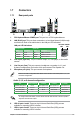

Table Of Contents
- Safety information
- About this guide
- P8H61-M2 series specifications summary
- Chapter 1: Product introduction
- Chapter 2: BIOS information

ASUS P8H61-M2 Series1-2
1.2 Motherboard overview
1.2.1 Motherboard layout
Place eight screws into the holes indicated by circles to secure the motherboard to the
chassis. DO NOT overtighten the screws! Doing so can damage the motherboard.
Ensure that you install the motherboard into the chassis in the correct orientation. The edge
with external ports goes to the rear part of the chassis.
Place this side towards
the rear of the chassis.
1.2.2 Layout contents
Connectors/Jumpers/Slots/LED Page Connectors/Jumpers/Slots/LED Page
1. ATX power connectors (24-pin EATXPWR, 4-pin ATX12V) 1-10 9. System panel connector (10-1 pin F_PANEL) 1-12
2. CPU and Chassis fan connectors (4-pin CPU_FAN, 3-pin
CHA_FAN)
1-11 10 Speaker connector (4- pin SPEAKER) 1-14
3. LGA775 CPU socket
1-3 11. Clear RTC RAM (3-pin CLRTC) 1-8
4. DDR3 DIMM slots
1-3 12. Standby power LED (SB_PWR) 1-1
5. Serial port connector (10-1 pin COM1)
1-11 13. USB connectors (10-1 pin USB78, USB910) 1-14
6. LPT connector (26-1 pin LPT)
1-12 14. Front panel audio connector (10-1 pin AAFP) 1-13
7. Chassis intrusion connector (4-1 pin CHASSIS)
1-15 15 Digital audio connector (4-1 pin SPDIF_OUT) 1-15
8. Serial ATA connectors (7-pin SATA3G1-4)
1-13
P8H61-M2/TPM/SI
PCIEX16_1
PCI1
PCI2
PCIEX1_1
C
HA
S
S
IS
AAFP
EATXPWR
CPU_FAN
CHA_FAN
C
LR
TC
S
P
E
A
K
E
R
Lithium Cell
CMOS Power
VIA
1708S
ASM
1083
RTL
8111E
EPU
ASM
1442
32Mb
BIOS
SB_PWR
SPDIF_OUT
22.9cm(9.0in)
24.4cm(9.6in)
LGA1155
Intel
®
H61
DDR3 DIMM_A1 (64bit, 240-pin module)
DDR3 DIMM_A2 (64bit, 240-pin module)
DDR3 DIMM_B1 (64bit, 240-pin module)
DDR3 DIMM_B2 (64bit, 240-pin module)
SATA3G_1SATA3G_3
SATA3G_2SATA3G_4
Super
I/O
COM1
TPM
ATX12V
LPT
USB910 USB78
F_PANEL
AUDIO
KB_USB56
LAN1_USB12
USB34
VGA
DVI
21 43 2 5
6
1
7
13 91011 8121415
The TPM chip is available in P8H61-M2/TPM/SI only.