A7V333 User Guide Motherboard ®
Checklist Product Name: Manual Revision: Release Date: A7V333 1.01 E1010 March 2002 Copyright © 2002 ASUSTeK COMPUTER INC. All Rights Reserved. No part of this manual, including the products and software described in it, may be reproduced, transmitted, transcribed, stored in a retrieval system, or translated into any language in any form or by any means, except documentation kept by the purchaser for backup purposes, without the express written permission of ASUSTeK COMPUTER INC. (“ASUS”).
About this guide Features This user manual contains complete information for installing the ASUS A7V333 motherboard. How this guide is organized • • • • • • • Chapter 1: Product introduction. A summary of product features and special attributes of new technologies. Chapter 2: Hardware information. A list of hardware setup procedures and descriptions of all jumpers and connectors on the motherboard. Chapter 3: Powering up. Describes the power up sequence with information on BIOS beep codes.
Contents Safeguards About this guide .............................................................................. iii How this guide is organized .................................................... iii Conventions used in this guide ............................................... iii Safety information ........................................................................... vi FCC/CDC statements .................................................................... vii ASUS contact information ........
Contents 3.3 Powering off the computer .................................................... 48 Chapter 4: BIOS setup ............................................................. 1 4.1 4.2 4.3 4.4 4.5 4.6 4.7 Managing and updating your BIOS ....................................... 49 4.1.1 Using the computer system for the first time ............ 49 4.1.2 Updating BIOS procedures ...................................... 51 BIOS Setup program .............................................................
Safety information Electrical safety • To prevent electrical shock hazard, disconnect the power cable from the electrical outlet before relocating the system. • When adding or removing devices to or from the system, ensure that the power cables for the devices are unplugged before the signal cables are connected. Disconnect all power cables from the existing system before you add a device. • Before connecting or removing signal cables from the motherboard, ensure that all power cables are unplugged.
FCC/CDC statements Federal Communications Commission Statement This device complies with FCC Rules Part 15. Operation is subject to the following two conditions: • • This device may not cause harmful interference, and This device must accept any interference received including interference that may cause undesired operation. This equipment has been tested and found to comply with the limits for a Class B digital device, pursuant to Part 15 of the FCC Rules.
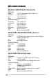
ASUS contact information ASUSTeK COMPUTER INC. (Asia-Pacific) Marketing Address: Telephone: Fax: Email: 150 Li-Te Road, Peitou, Taipei, Taiwan 112 +886-2-2894-3447 +886-2-2894-3449 info@asus.com.tw Technical Support Tel (English): Tel (Chinese): Fax: Email: Newsgroup: WWW: FTP: +886-2-2890-7123 +886-2-2890-7113 +886-2-2890-7698 tsd@asus.com.tw cscnews.asus.com.tw www.asus.com.tw ftp.asus.com.
Chapter 1 Product introduction
ASUS A7V333 motherboard
Welcome! Thank you for buying the ASUS® A7V333 motherboard! The A7V333 is powered by AMD® Athlon™, Athlon™ XP and Duron™ processors and supplies advanced features to ensure long-lasting, superlative performance. The ASUS® A7V333 motherboard is the prime choice for home PCs and workstations.
1.2 Core Specifications The A7V333 motherboard is designed and assembled according to the highest standards. This ASUS motherboard represents the latest advances and offers users the finest componentry available today... AMD® Athlon™/ Athlon™ XP and Duron™ Socket A (462) Processor North Bridge Chipset: the VIA® KT333 supports AGP 4X/2X mode, 133/100MHz Front Side Bus, and the fastest 333/266/200MHz memory bus.
1.3 Special Features Easy Overclocking • Quickly adjust CPU frequency multiples with BIOS in JumperFree™ Mode • Adjustable FSB/MEM/PCI frequency ratio • Stepless Frequency Selection (SFS) for fine-tuning system bus frequency from at 1MHz increments • Optimal system performance available with BIOS built-in Turbo Mode • Adjustable Vcore Voltage and VIO • Alternatively, easy-to-use DIP switches permit manual adjustment of the processor external/internal frequency settings. C.O.
1.4 Motherboard Components Before installing the A7V333 motherboard, take time to familiarize yourself with its configuration: understanding the motherboard makes upgrading easy. Sufficient knowledge of specifications prevents accidental damage. Processor Support Chipsets Main Memory Expansion Slots System I/O Hardware Monitoring Special Feature Audio Features Power Form Factor 4 Location Socket A for AMD Athlon and Duron Processors ....... 2 Feature Setting DIP Switches .............................
1.4.
Chapter 2 Hardware information
ASUS A7V333 motherboard
2.1 Motherboard installation The A7V333 uses the ATX form factor, measuring 24.5 cm (9.6 in.) x 30.5 cm (12 in.) - a standard fit for most large chassis. WARNING! Unplug the power cord before installing the motherboard. Failure to do so may cause you physical injury and damage motherboard components. 2.1.1 Placement direction When installing the motherboard, take care to orient the chassis correctly: The edge with external ports goes to the rear part of the chassis. Refer to the image below.
2.2 Motherboard layout 24.5cm (9.6in) PS/2KBMS T: Mouse B: Keyboard VID4 VID3 VID2 VID1 KBWK USB01_PWR SPEECH USB1.
2.2.1 Layout contents CPU, Memory and Expansion Slots 1) Socket 462 p. 12 CPU Support 2) DIMM 1/2/3 p. 14 System Memory Support 3) PCI 1/2/3/4/5 p. 16 32-bit PCI Bus Expansion Slots 4) AGP PRO p. 18 Accelerated Graphics Slot Motherboard Settings (Switches and Jumpers) 1) JEN p. 19 JumperFree Mode Setting (Disable/Enable) 2) DIP_SW p. 20 CPU External Frequency Selection (Switches 1–6) 3) RAID_EN p. 21 RAID Controller (Enable/Disable) 4) ROMSIP p. 21 ROM Setting (Hardware/Software) 5) VID1-4 p.
13) ATXPWR 14) SMB 15) CD / AUX / MODEM 16) JTPWR 17) SMARTCARD 18) SD, MS 19) GAME 20) SPDIF_C 21) USB20_34, USB2_3 22) CHASSIS 23) BACK_LT / BACK_RT 24) LINE_IN 25) IPANEL 26) 1394HEAD 27) PLED (PANEL) 28) KEYLOCK (PANEL) 29) SPEAKER (PANEL) 30) MLED (PANEL) 31) SMI (PANEL) 32) PWR (PANEL) 33) RESET (PANEL) 10 p. 36 p. 36 p. 37 p. 34 p. 38 p. 38 p. 39 p. 39 p. 40 p. 41 p. 42 p. 42 p. 43 p. 43 p. 44 p. 44 p. 44 p. 44 p. 44 p. 44 p.
2.3 Before you proceed Take note of the following precautions before you install motherboard components or change any motherboard settings. CAUTION! 1. Unplug the power cord from the wall socket before touching any component. 2. Use a grounded wrist strap or touch a safely grounded object or to a metal object, such as the power supply case, before handling components to avoid damaging them due to static electricity. 3. Hold components by the edges and do not to touch the ICs on them. 4.
2.4 Central Processing Unit (CPU) 2.4.1 Overview The motherboard provides a Socket A (462) for CPU installation. AMD processors offer gigahertz speeds to support all the latest computing platforms and applications. The A7V333 supports Athlon™ XP processors with “QuantiSpeed” data processing, large data caches, 3D enhancements and 266MHz bus speeds. CPU NOTCH TO INNER CORNER AMD™ CPU A7V333 ® CPU NOTCH LEVER LOCK A7V333 Socket A Each AMD CPU has a “marked” corner.
2.4.2 Installing the CPU Follow these steps to install a CPU: 1. Locate the Socket 462 and open it by pulling the lever gently sideways away from the socket. Then lift the lever upwards. The socket lever must be fully opened (90 to 100 degrees). 2. Insert the CPU with the correct orientation. The notched or golden corner of the CPU must be oriented toward the inner corner of the socket base nearest to the lever hinge. CAUTION! The CPU should drop easily into place.
2.5 System memory 2.5.1 Overview This motherboard uses only Double Data Rate (DDR) Synchronous Dynamic Random Access Memory (SDRAM) Dual Inline Memory Modules (DIMMs). These sockets support up to 3GB system memory using non-ECC 200/266/ 333MHz DIMMs. Each DIMM socket/module is two-sided: each side defines one “row” of memory. DIMMs come in combinations of single or double-sided types ranging through 64MB, 128MB, 256MB, 512MB and 1GB to form a total memory size of 64MB to 3GB.
2.5.2 Memory configurations Install DIMMs in any of the following combinations. DIMM Location 184-pin DIMM (DDR) Socket 1 (Rows 0&1) 64MB, 128MB, 256MB, 512MB, 1GB x1 Socket 2 (Rows 2&3) 64MB, 128MB, 256MB, 512MB, 1GB x1 Socket 3 (Rows 4&5) 64MB, 128MB, 256MB, 512MB, 1GB x1 Total system memory (Max. 3GB) Total Memory = 2.5.3 Installing a DIMM CAUTION! Make sure to unplug the power supply before adding or removing DIMMs or other system components.
2.6 Expansion slots The motherboard has five PCI slot and one Accelerated Graphics Port (AGP) slot.. The following sub-sections describe the slots and the expansion cards that they support. WARNING! Unplug your power supply when adding or removing expansion cards or other system components. Failure to do so may cause you physical injury and damage motherboard components. 2.6.1 Installing an expansion card Follow these steps to install an expansion card. 1.
IMPORTANT! When using PCI cards on shared slots, ensure that the drivers support “Share IRQ” or that the cards do not need IRQ assignments. Otherwise, conflicts will arise between the two PCI groups, making the system unstable and the card inoperative.
2.6.3 PCI slots Five 32-bit PCI slots are available on this motherboard. The slots support PCI cards such as a LAN card, SCSI card, USB card, and other cards that comply with PCI specifications. This figure shows a typical PCI card installed into a slot: 2.6.4 AGP PRO slot This motherboard provides an Accelerated Graphics Port (AGP PRO) slot to support AGP graphics cards. Take note of the notches on the card golden fingers to ensure that they fit the AGP slot on your motherboard.
2.7 Switches and jumpers The jumpers on the motherboard allow you to change some feature settings to suit your customized system configuration. Motherboard Frequency Settings (DIP Switches) The motherboard frequency is adjusted through the DSW switches. The illustration below shows the default position: SYSCLK ON ON OFF A7V333 ® A7V333 DIP Switches 1 2 3 4 5 6 1.Frequency Selection 2.Frequency Selection 3.Frequency Selection 4.Frequency Selection 5.Frequency Selection 6.
2) CPU External Frequency Selection (DIP_SW Switches 1–4) This option tells the clock generator what frequency to send to the CPU, DRAM, and the PCI bus. This allows the selection of the CPU’s External frequency (or BUS Clock). The BUS Clock multiplied by the Frequency Multiple equals the CPU’s Internal frequency (the advertised CPU speed).
3) RAID Controller (3 pin RAID_EN) This jumper enables or disables the Promise IDE-RAID controller. The default setting, [1-2], enables both the IDE 133 and RAID functions. To disable it, reset the jumper cap to [2-3]. This jumper overrides all BIOS settings. RAID_EN 1 2 A7V333 ® 2 3 ENABLE (Default) DISABLE A7V333 PROMISE Setting 4) ROM Setting (3 pin ROMSIP) This jumper selects the source for data to set functional parameters for the CPU.
5) Voltage Regulator Output Setting (4x3 pin VID1 - 4) This jumpers allow you to manually adjust the CPU core voltage. For each jumper setting, there are two voltage options, depending on the CPU used. The factory default sets all jumpers to [2-3], for use with JumperFree™ mode. 1 2 3 VID4 VID3 VID2 VID1 1 2 3 1.85/1.825Volts A7V333 ® VID4 VID3 VID2 VID1 1.8/1.775Volts 1 2 3 JumperFree (Default) 1 2 3 1 2 3 1.75/1.725Volts 1.7/1.
7) Keyboard Wake Up (3 pin KBWK) This allows you to disable or enable the keyboard power up function. Set this jumper to Enable if you wish to use your keyboard (by pressing ) to power up your computer. This feature requires an ATX power supply that can supply at least 300mA on the +5VSB lead. The default is set to Enable. (The computer will not power ON if you set this to Enable but do not have the correct ATX power supply.
8) USB 2.0 Compliant Device Enable (3 pin USB) This jumper enables or disables the Universal Serial Bus (USB) 2.0 capability. The default is set to enable [1-2] for use with USB 2.0 compliant devices. NOTE: This jumper activates rear panel ports USB20_12. USB_EN 2 3 1 2 A7V333 ® A7V333 USB Setting USB2.0 ENABLE (Default) USB2.0 DISABLE 9) USB Wakeup Enable (2x3 pin USBWP2_EN, USBWP1_EN) By default, these jumpers enable Wakeup power to the USB ports.
10) USB Device Wake-up (2x3 pin USB01_PWR/USB23_PWR) Set these jumpers to +5V to allow wake up from the S1 sleep state (CPU stopped; RAM refreshed; system running in low power mode) using the connected USB devices. Set to +5VSB to allow wake up from S3 sleep state (no power to CPU; RAM in slow refresh; power supply in reduced power mode). The default setting for the three jumpers is 1-2 to select +5V (because not all computers have the appropriate power supply).
11) IEEE-1394 Device Enable (3 pin 1394_En) This jumper opens the circuit to the 1394 headers. By default, [1-2] the circuit is already open. Set to pins [2-3] to disable power to the 1394 header. 1394_EN 1 2 2 3 A7V333 ® 1394 ENABLE (Default) 1394 DISABLE A7V333 1394HEAD Setting 12) MS SD Device Enable (3 pin MS_SD_EN) This jumper opens the circuit to the MS SD headers. By default, [1-2] the circuit is already open. Set to pins [2-3] to disable power to the MS SD header.
BCS1 BCS2 BCS1 BCS2 1 2 2 3 13) Bass Center Setting (2x3 pin CENTER/BASS, BASS/CENTER) Use these jumpers in conjunction with the C-Media PCI Audio Driver and to adjust output for 4 or 6 speaker audio. No audio standard exists for the three pick-up surfaces on male audio jacks, therefore it may be necessary to switch jumpers from the default position, type 1, to type 2, in order to reroute signals among the internal leads in the Line-In, Line-Out, Mic female sockets.
15) Audio Setting (3 pin Audio_En) The onboard 6 channel audio chip may be enabled or disabled using these jumpers. The default, [1-2], enables the audio setting. Disable the onboard audio system if using a PCI audio card on any of the expansion slots. AUDIO_EN A7V333 ® 1 2 A7V333 Audio Codec Setting Enable (Default) 2 3 Disable 16) Clear RTC RAM (CLR_RTC) This jumper allows you to clear the Real Time Clock (RTC) RAM in CMOS.
2.8 Connectors This section describes and illustrates the internal connectors on the motherboard. WARNING! Some pins are used for connectors or power sources. These are clearly distinguished from jumpers in the Motherboard Layout. Placing jumper caps over these connector pins will cause damage to your motherboard. IMPORTANT! Ribbon cables should always be connected with the red stripe to Pin 1 in the connector scoket.
3) Universal Serial Bus Ports 0, 1, 2 & 3 (Black two 4-pin USB) Four USB ports are available for connecting USB devices. USB 1 USB 0 USB 2 (Universal Serial Bus “2.0”) USB 1 (Universal Serial Bus “1.1”) 4) Parallel Port (Burgundy 25-pin PRINTER) You can enable the parallel port and choose the IRQ through Onboard Parallel Port (see 4.4.2 I/O Device Configuration). NOTE! Serial printers must be connected to the serial port.
6) Audio Connectors (Three 1/8” AUDIO) (optional) The Line Out (lime) connects a headphone or speakers. The Line In (light blue) connects a tape players or other audio sources. The Mic (pink) connects a microphone. NOTE! The functions of the audio connectors Line Out, Line In, and Mic change when the 6-channel audio feature is enabled. Refer to Chapter 5. SOFTWARE SETUP.
7) IDE Activity LED (2-pin IDELED) This connector supplies power to the cabinet’s IDE activity LED. Read and write activity by devices connected to the Primary or Secondary IDE connectors cause the IDE LED to light up. TIP: If the case-mounted LED does not light, try reversing the 2-pin plug. IDELED A7V333 ® A7V333 IDE Activity LED 8) Floppy Disk Drive Connector (34-1 pin FLOPPY) This connector supports the provided floppy drive ribbon cable.
9) Primary (Blue) / Secondary (Black) IDE Connectors (40-1 pin PRIMARY IDE and SECONDARY IDE) (40-1 pin PROMISE IDE1 and PROMISE2 IDE) The Primary and Secondary IDE connectors support the IDE hard disk ribbon cables supplied with the motherboard. Connect the cable’s blue connector to the motherboard’s primary IDE connector (recommended) or the secondary IDE connector. Connect the opposite end of the cable to your UltraDMA133/ 100/66 device (hard disk drive).
10) CPU Fan, Power Fan, and Chassis Fan Connectors (3x3 pin CPU_, PWR_, CHA_FAN) Three fan connectors support cooling fans of 350mA (4.2 Watts) or less. Orient the fans so that airflow flows across the onboard heat sinks instead of expansion slots. The fan wiring and plug vary depending on the type employed. Connect the fan cable to the connector, ensuring that the black wire matches the ground pin. (Use the “Rotation” signal only with a specially designed fan with a rotation signal.
11) Infrared Module Connector (10-1 pin IR_CON) This connector supports an optional wireless transmitting and receiving infrared module. This module mounts to a small opening on system cases that support it. Configure the IR setting through UART2 Use Infrared to select whether UART2 is directed for use with COM2 or IrDA (see 4.4.2 I/O Device Configuration). Use the five pins as shown and connect a ribbon cable from the module to the motherboard SIR connector according to the pin definitions.
13) Power Supply Connectors (20-pin block ATXPWR) This connector supports an ATX 12V power supply. The plug from the power supply fits in only one orientation. Push down firmly ensuring that the pins are aligned. IMPORTANT! Make sure that the ATX 12V power supply (minimum recommended wattage: 230W) can supply at least 10mA on the +5-volt standby lead (+5VSB). The system may become unstable and may experience difficulty powering up if the power supply is inadequate.
15) Internal Audio Connectors (4 pin CD, AUX, MODEM) (optional) These connectors allow you to receive stereo audio input from sound sources as a CD-ROM, TV tuner, or MPEG card. The MODEM connector allows the onboard audio to interface with a voice modem card with a similar connector. It also allows the sharing of mono_in (such as a phone) and a mono_out (such as a speaker) between the audio and a voice modem card.
17) Smart Card Reader Connector (14-1 pin SMARTCARD) This connector accommodates a Smart Card Reader that allows you to conveniently make transactions such as financial, health care, telephony, or traveling services through a Smart Card user interface software. When using this connector, configure the UART2 Use As parameter in BIOS to set UART2 for use with Smart Card. See Advanced BIOS sub-menu, “I/O Device Configuration” for details.
19) Game Connector (16-1 pin GAME) A7V333 ® 9 +5V J2B1 J2CX MIDI_OUT J2CY J2B2 MIDI_IN This connector supports an external game port. An example of a PCI game port is illustrated. 16 1 A7V333 Game Connector +5V J1B1 J1CX GND GND J1CY J1B2 +5V GAME 8 20) Digital Audio Interfaces (6-1 pin SPDIF_C) These connectors supply an SPDIF audio cable that outputs digital instead of analog sound from CD-ROM, DVD-ROM, CD-RW, and advanced sound cards such as SoundBlaster Live.
GND LDP2 LDM2 USB+5V 21) USB Headers (10-1 pin USB20_34, USB2_3) If the USB port connectors on the back panel are inadequate, two USB headers are available for four additional USB port connectors. Connect a 2-port USB connector set to a USB header and mount the USB bracket to an open slot in the chassis. The USB20_34 header supports the USB 2.0 protocol and the USB2_3 header supports the USB 1.1 header. USB20_34 A7V333 ® 10 6 5 1 NC GND LDP1 LDM1 USB+5V (Blue) A7V333 USB 2.
22) Chassis Open Alarm Lead (4-1 pin CHASSIS) This lead is intended for a chassis designed to support intrusion detection. The lead requires an external detection mechanism such as a chassis intrusion monitor/sensor or microswitch. When any chassis component is removed, the sensor is triggered and a high-level signal is sent to this lead to record a chassis intrusion event. The event is then be processed by software such as LDCM.
BLOL FLOL BLOR FLOR 23) Line-out Selector Jumpers (4 pin BACK_LT / BACK_RT) By default, these jumpers are shorted (jumpers on) to route the signal from the audio controller to the rear panel Line Out jack to make it available for audio out devices such as speakers or a headphone.
25) ASUS Front Panel Audio Connector (10-1 pin IPANEL) Connect the audio cable for front panel audio control. ® BLINE_OUT_R +5VA AGND A7V333 BLINE_OUT_L Line out_L NC Line out_R MICPWR MIC2 IPANEL A7V333 Front Panel Audio Connector 26) IEEE-1394 Header (8-pin 1394HEAD) (Optional) This header supports an IEEE-1394 serial connector cable set that mounts to a standard expansion slot in the computer case. 1394-compliant internal fixed disk drives may also be connected to these headers.
The following 20-pin PANEL illustration is for items 27-33. A7V333 ® Message LED SMI Lead A7V333 System Panel Connectors Reset Ground +5 V MLED ExtSMI# Ground PWR Ground +5 V PLED Keylock Ground Power LED Speaker Connector +5V Ground Ground Speaker Keyboard Lock Reset SW ATX Power Switch* * Requires an ATX power supply. 27) System Power LED Lead (3-1 pin PLED) This 3-1 pin connector supplies the system power LED.
Chapter 3 Powering up
ASUS A7V333 motherboard
3.1 Starting up for the first time 1. After making all the connections, replace the system case cover. 2. Be sure that all switches are off. 3. Connect the power cord to the power connector at the back of the system chassis. 4. Connect the power cord to a power outlet that is equipped with a surge protector. 5. Turn on the devices in the following order: a. Monitor b. External SCSI devices (starting with the last device on the chain) c.
3.2 Vocal POST Messages This motherboard includes the Winbond speech controller to support a special feature called the ASUS POST Reporter™. This feature gives you vocal POST messages and alerts to inform you of system events and boot status. In case of a boot failure, you will hear the specific cause of the problem. These POST messages are customizable using the Winbond Voice Editor software that came with your package. You can record your own messages to replace the default messages.
POST Message Action No keyboard detected • Check your keyboard if properly connected to the purple PS/2 connector on the rear panel. • See section “1.4.1 Component Locations” for the location of the keyboard connector. No floppy disk detected • Make sure you have connected a floppy disk to the floppy disk connector on the motherboard. • See section “2.8 Connectors.” No IDE hard disk detected • Make sure you have connected an IDE hard disk drive to the one of the IDE connectors on the motherboard.
3.3 Powering off the computer You must first exit the operating system and shut down the system before switching off the power. For ATX power supplies, you can press the ATX power switch after exiting or shutting down the operating system. If you use Windows 95/98/2000/XP, click the Start button, click Shut Down, then click the OK button to shut down the computer. The power supply should turn off after Windows shuts down.
Chapter 4 BIOS setup
ASUS A7V333 motherboard
4.1 Managing and updating your BIOS 4.1.1 Using the computer system for the first time It is recommended that you save a copy of the original motherboard BIOS along with a Flash Memory Writer utility (AFLASH.EXE) to a bootable floppy disk in case you need to reinstall the BIOS later. AFLASH.EXE is a Flash Memory Writer utility that updates the BIOS by uploading a new BIOS file to the programmable flash ROM on the motherboard. This file works only in DOS mode.
Using AFLASH from a Floppy Disk: 1. Type FORMAT A:/S at the DOS prompt to create a bootable system disk. DO NOT copy AUTOEXEC.BAT and CONFIG.SYS to the disk. 2. Type COPY D:\AFLASH\AFLASH.EXE A:\ (assuming D is your CD-ROM drive) to copy AFLASH.EXE to the boot disk you created. NOTE! AFLASH works only in DOS mode. It does not function in the DOS prompt within Windows, and does not function with certain memory drivers that may be loaded when you boot from the hard drive.
4.1.2 Updating BIOS procedures CAUTION! Update the BIOS only if you have problems with the motherboard and you are sure that the new BIOS revision will solve your problems. Careless updating may result to more problems with the motherboard! 1. FTP) (see ASUS CONTACT INFORMATION on page x for details) and save to the boot floppy disk you created earlier. 2. Boot from the floppy disk. 3. At the “A:\” prompt, type AFLASH and then press . 4. At the Main Menu, type 2 then press .
7. The utility starts to program the new BIOS information into the Flash ROM. The boot block is updated automatically only when necessary. This minimizes the possibility of boot problems in case of update failures. When the programming is done, the message “Flashed Successfully” appears. 8. Follow the onscreen instructions to continue. WARNING! If you encounter problems while updating the new BIOS, DO NOT turn off the system because this may cause boot problems.
4.2 BIOS Setup program This motherboard supports a programmable EEPROM that you can update using the provided utility described in section “4.1 Managing and updating your BIOS.” Use the BIOS Setup program when you are installing a motherboard, reconfiguring your system, or prompted to “Run Setup”. This section explains how to configure your system using this utility. Even if you are not prompted to use the Setup program, you may want to change the configuration of your computer in the future.
4.2.1 BIOS menu bar The top of the screen has a menu bar with the following selections: MAIN Use this menu to make changes to the basic system configuration. ADVANCED Use this menu to enable and make changes to the advanced features. POWER Use this menu to configure and enable Power Management features. BOOT Use this menu to configure the default system device used to locate and load the Operating System. EXIT Use this menu to exit the current menu or to exit the Setup program.
General help In addition to the Item Specific Help window, the BIOS setup program also provides a General Help screen. You may launch this screen from any menu by simply pressing or the + combination. The General Help screen lists the legend keys and their corresponding functions. Saving changes and exiting the Setup program See “4.7 Exit Menu” for detailed information on saving changes and exiting the setup program.
4.3 Main Menu When you enter the Setup program, the following screen appears. System Time [XX:XX:XX] Sets the system to the time that you specify (usually the current time). The format is hour, minute, second. Valid values for hour, minute and second are Hour: (00 to 23), Minute: (00 to 59), Second: (00 to 59). Use the or + keys to move between the hour, minute, and second fields. System Date [XX/XX/XXXX] Sets the system to the date that you specify (usually the current date).
4.3.1 Primary and Secondary Master/Slave Type [Auto] Select [Auto] to automatically detect an IDE hard disk drive. If automatic detection is successful, Setup automatically fills in the correct values for the remaining fields on this sub-menu. If automatic detection fails, this may be because the hard disk drive is too old or too new. If the hard disk was already formatted on an older system, Setup may detect incorrect parameters.
[User Type HDD] Manually enter the number of cylinders, heads and sectors per track for the drive. Refer to the drive documentation or on the drive label for this information. NOTE! After entering the IDE hard disk drive information into BIOS, use a disk utility, such as FDISK, to partition and format new IDE hard disk drives. This is necessary so that you can write or read data from the hard disk. Make sure to set the partition of the Primary IDE hard disk drives to active.
Translation Method [LBA] Select the hard disk drive type in this field. When Logical Block Addressing (LBA) is enabled, the 28-bit addressing of the hard drive is used without regard for cylinders, heads, or sectors. Note that LBA Mode is necessary for drives with more than 504MB storage capacity. Configuration options: [LBA] [LARGE] [Normal] [Match Partition Table] [Manual] Cylinders This field configures the number of cylinders. Refer to the drive documentation to determine the correct value.
SMART Monitoring [Disabled] This field allows you to enable or disable the S.M.A.R.T. (Self-Monitoring, Analysis and Reporting Technology) system that utilizes internal hard disk drive monitoring technology. This parameter is normally disabled because the resources used in the SMART monitoring feature may decrease system performance. Configuration options: [Disabled] [Enabled] PIO Mode [0] This option lets you set a PIO (Programmed Input/Output) mode for the IDE device.
4.3.2 Keyboard Features Boot Up NumLock Status [On] This field enables users to activate the Number Lock function upon system boot. Configuration options: [Off] [On] Keyboard Auto-Repeat Rate [12/Sec] This controls the speed at which the system registers repeated keystrokes. Options range from 6 to 30 characters per second.
Language [English] This field displays the BIOS language version. Supervisor Password [Disabled] / User Password [Disabled] These fields allow you to set passwords. To set a password, highlight the appropriate field and press . Type in a password then press . You can type up to eight alphanumeric characters. Symbols and other characters are ignored. To confirm the password, type the password again and press . The password is now set to [Enabled].
4.4 Advanced Menu CPU Speed [Manual] When the motherboard is set to JumperFree™ mode, this field allows you to select the internal frequency of the CPU. Select [Manual] if you want to make changes to the two subsequent fields. Note that selecting a frequency higher than the CPU manufacturer recommends may cause the system to hang or crash. CPU Frequency Multiple (when CPU Speed is set to [Manual]) This field applies to unlocked processors only.
CPU VCore Setting [Auto] This field determines if the CPU Vcore is automatically scaled or set manually by the user. The default for this field is [Auto], so the CPU vcore voltage is set for maximum performance without stressing the CPU. Configuration options: [Manual] [Auto] CPU VCore [1.850V] When the CPU VCore Setting parameter is set to [Manual], this item allows you to select a specific CPU core voltage. This field is not accessible when the CPU VCore Setting parameter is set to [Auto].
4.4.1 Chip Configuration (Scroll down to view all items on the menu.) SDRAM Configuration [By SPD] This parameter allows you to set the optimal timings for items 2–5, depending on the memory modules that you are using. The default setting is [By SPD], which configures items 2–5 by reading the contents in the SPD (Serial Presence Detect) device. The EEPROM on the memory module stores critical information about the module, such as memory type, size, speed, voltage interface, and module banks.
SDRAM Active to Precharge Delay [6T] This item controls the number os SDRAM clocks used for SDRAM parameters. SDRAM 1T Command Control [Disabled] This item controls the pulse signal for DDR commands. The [Disabled] default is equivalent to 2T and enabled, to 1T.
Onboard PCI IDE Controller [Both] This field allows you to enable either the primary IDE channel or secondary IDE channel, or both. You can also set both channels to [Disabled]. Configuration options: [Both] [Primary] [Secondary] [Disabled] S2K Bus Driving Strength [Auto] This item controls the host bus between the AMD K7 processor and the north bridge. Configuration options: [Auto] [Manual] S2K Strobe P Control [2] S2K Strobe N Control [3] Useful test parameters.
4.4.2 I/O Device Configuration Onboard FDC Swap A & B [No Swap] This field reverses the hardware drive letter assignments of floppy disk drivers. Configuration options: [No Swap] [Swap AB] Floppy Disk Access Control [R/W] This field sets the capacity of the floppy disk drivers to read and/or write. Configuration options: [R/W] [Read only] Onboard Serial Port 1 [3F8H/IRQ4] Onboard Serial Port 2 [2F8H/IRQ3] These fields set the addresses for the onboard serial connectors.
Parallel Port Mode [ECP+EPP] This field sets the operation mode of the parallel port. [Normal] allows normalspeed operation but in one direction only; [EPP] allows bidirectional parallel port operation; [ECP] allows the parallel port to operate in bidirectional DMA mode; [ECP+EPP] allows normal speed operation in a two-way mode. Configuration options: [Normal] [EPP] [ECP] [ECP+EPP] ECP DMA Select [3] This field configures the parallel port DMA channel for the selected ECP mode.
4.4.3 PCI Configuration Slot 1/5, 2, 3, 4 IRQ [Auto] These fields automatically assign the IRQ for each PCI slot. The default setting for each field is [Auto], which utilizes auto-routing to determine IRQ assignments. Configuration options: [Auto] [NA] [3] [4] [5] [7] [9] [10] [11] [12] [14] [15] PCI/VGA Palette Snoop [Disabled] Some non-standard VGA cards, like graphics accelerators or MPEG video cards, may not show colors properly. Setting this field to [Enabled] corrects this problem.
4.4.3.1 Onboard PCI Devices Control Onboard PCI Audio [Enabled] [Auto] allows the BIOS to detect whether you are using any audio device. If an audio device is detected, the onboard audio controller is enabled; if no audio device is detected, the controller is disabled. If there are conflicts with the onboard modem/audio controller, set the appropriate field to [Disabled].
4.4.3.2 PCI IRQ Resource Exclusion IRQ XX Used By ISA [No/ICU] These fields indicate whether or not the displayed IRQ for each field is being used by a legacy (non-PnP) ISA card. The setting [No/ICU] for an IRQ field indicates that you are using the ISA Configuration Utility (ICU), and that this particular IRQ is NOT required by a legacy ISA card. Set the IRQ field to [Yes] if you install a legacy ISA card that requires a unique IRQ and you are NOT using ICU Also, it is required to reserve the IRQ, ie.
4.5 Power Menu The Power menu allows you to reduce power consumption. This feature turns off the video display and shuts down the hard disk after a period of inactivity. Power Management [User Defined] This field allows you to activate or deactivate the automatic power saving features. When set to [Disabled], the power management features do not function regardless of the other settings on this menu.
Video Off Option [Suspend -> Off ] This field determines when to activate the video off feature for monitor power management. Configuration options: [Always On] [Suspend -> Off] Video Off Method [DPMS OFF] This field defines the video off features. The Display Power Management System (DPMS) feature allows the BIOS to control the video display card if it supports the DPMS feature. [Blank Screen] only blanks the screen. Use this for monitors without power management or “green” features.
4.5.1 Power Up Control AC PWR Loss Restart [Disabled] This allows you to set whether or not to reboot the system after power interruptions. [Disabled] leaves your system off while [Enabled] reboots the system. [Previous State] sets the system back to the state it was before the power interruption. Configuration options: [Disabled] [Enabled] [Previous State] Wake/Power Up On Ext.
Power On By PS/2 Mouse [Disabled] When set to [Enabled], this parameter allows you to use the PS/2 mouse to turn on the system. This feature requires an ATX power supply that provides at least 1A on the +5VSB lead. Configuration options: [Disabled] [Enabled] Automatic Power Up [Disabled] This allows an unattended or automatic system power up. You may configure your system to power up at a certain time of the day by selecting [Everyday] or at a certain time and day by selecting [By Date].
4.5.2 Hardware Monitor MB Temperature [xxxC/xxxF] CPU Temperature [xxxC/xxxF] POWER Temperature [N/A] The onboard hardware monitor automatically detects the MB (motherboard) and CPU temperatures. CPU Fan Speed [xxxxRPM] POWER Fan Speed [N/A] CHASSIS Fan Speed [N/A] The onboard hardware monitor automatically detects the CPU and chassis fan speeds in rotations per minute (RPM). VCORE Voltage, +3.
4.6 Boot Menu Boot Sequence The Boot menu allows you to select among the four possible types of boot devices listed using the up and down arrow keys. By using the <+> or key, you can promote devices and by using the <-> key, you can demote devices. Promotion or demotion of devices alters the priority which the system uses to search for a boot device on system power up. Configuration fields include Removable Devices, IDE Hard Drive, ATAPI CD-ROM, and Other Boot Device.
Plug & Play O/S [No] This field allows you to use a Plug-and-Play (PnP) operating system to configure the PCI bus slots instead of using the BIOS. When [Yes] is selected, interrupts may be reassigned by the OS. If you installed a non-PnP OS or if you want to prevent reassigning of interrupt settings, keep the default setting [No]. Configuration options: [No] [Yes] Reset Configuration Data [No] The Extended System Configuration Data (ESCD) contains information about non-PnP devices.
4.7 Exit Menu When you have made all of your selections from the various menus in the Setup program, save your changes and exit Setup. Select Exit from the menu bar to display the following menu. NOTE! Pressing does not immediately exit this menu. Select one of the options from this menu or from the legend bar to exit. Exit Saving Changes Once you are finished making your selections, choose this option from the Exit menu to ensure the values you selected are saved to the CMOS RAM.
Load Setup Defaults This option allows you to load the default values for each of the parameters on the Setup menus. When you select this option or if you press , a confirmation window appears. Select [Yes] to load default values. Select Exit Saving Changes or make other changes before saving the values to the non-volatile RAM. Discard Changes This option allows you to discard the selections you made and restore the previously saved values. After selecting this option, a confirmation appears.
82 Chapter 4: BIOS Setup
Chapter 5 Software support
ASUS A7V333 motherboard
5.1 Install an operating system This motherboard supports Windows 98/ME/NT/2000/XP and OS/2 operating system (OS). Always install the latest OS version and corresponding updates so you can maximize the features of your hardware. 5.1.1 Windows 98 first time installation When you start Windows for the first time after installing the motherboard, Windows 98 detects all Plug-n-Play devices devices. Follow the Add New Hardware wizard to install the necessary device drivers.
5.3 A7V333 Motherboard Support CD NOTE: The support CD contents are subject to change without notice. To begin using your support CD disc, just insert it into your CD-ROM drive and the support CD installation menu should appear. If the menu does not appear, double-click or run D:\ASSETUP.EXE (assuming that your CD-ROM drive is drive D:). 5.3.1 Installation Menu • • • • • • • • • • VIA 4 in 1 drivers: Installs PCI Bus Master IDE Driver, VIA AGP Driver, VIA INF Driver, and IRQ Routing Driver.
• • • • • • • • ASUS Screen Saver: Installs a nifty ASUS screen saver. ITE GSM Editor: Installs the GSM SIM card editing application. Winbond Voice Editor: Installs an application to record and customize audio “wave” files for use with the ASUS Post Reporter™. E-Color 3Deep: Installs graphical driver and an application for tuning the quality of color output from CRT and LCD monitors.
5.4 Using the Promise Chip for RAID 0 or 1 The Promise ® chip, PDC20276, onboard the A7V333, offers a high performance Redundant Array of Independent Disks (RAID) configuration that supports only UltraDMA-133/100/66/33, EIDE or FastATA-2 hard disks. After connecting two hard disks to the motherboard, activating either RAID 0 or 1 function is easily configured through the MBFastTrak133™ “Lite” firmware BIOS during boot up.
5.4.1 Installing the Hard Disks The RAID 0 setting allows users to reformat two hard disks with the same new OS simultaneously. RAID 1 arrays can use a pre-existing hard disk along with a blank hard disk, or two new hard disks. 1. Install the first and second hard disk into the hard disk bays of your system. Connect each hard disk drive with a separate UltraDMA/100 cable, one to the Promise IDE1 connector, and the other to the Promise IDE2 connector onboard the A7V333.
5.4.3 Creating a RAID 0 Array 1. In the FastBuild™ Utility Main Menu, select Auto Setup [1]. The screen below is displayed. The Auto Setup Options Menu configures hard disks for RAID 0 and RAID 1 arrays. These selections assign all available drives that are appropriate for the new array and configures data formats and the IDE channels. FastBuild (tm) Utility 1.31 (c) 1996-2000 Promise Technology, Inc.
5.4.4 Creating a RAID 1 Array 1. In the FastBuild™ Utility Main Menu, select Auto Setup [1]. FastBuild (tm) Utility 1.31 (c) 1996-2000 Promise Technology, Inc. Optimize Array for: [ Auto Setup Options Menu ] Security Typical Application to use: Not Available [ Array Setup Configuration ] Mode ........................................ Mirror Spare Drive.................................. 0 Drive(s) Used in Array....................... 2 Array Disk Capacity (size in MB).............
5. The utility prompts: Please Select A Source Disk. Choose the pre-existing hard disk as the source and then a new, blank hard disk as the target. Then select to save the selection. The utility prompts a choice between to continue and to stop and escape. Choosing begins to duplicate the source hard disk onto the target hard disk. 6. To configure two new blank hard disks in a RAID 1 array, choose for Create Only; (At step 3).
5.4.5 Other FastBuild Utility Commands Command options 3-6 on the FastBuild™ Utility Main Menu are not required for setting up an array, but they are useful for reconfiguring an array: View Array (3): View the drive assignments of hard disks in an array. Delete Array (4): Deletes an array to reconfigure the system. Deleting an array does not remove information on the hard disks. If an array is deleted by mistake, recover it immediately by redefining it as the deleted array.
8. Confirm the command to copy data from the intact source hard disk onto a new replacement hard disk. A progress gauge displays the copy progress for the duration of the task. 9. After the rebuild is complete, the user is prompted to reboot the system. Controller Configuration (6): Default for Controller Configuration is: [enabled]. 5.4.6 Alternative Set Ups and Other Details Hot Spares A hot spare hard disk may be installed to support a RAID 1 array.
5.5 Manual Installation of IDE/RAID Drivers The A7V333 support CD contains several IDE and RAID 0 or 1 drivers in the Promise folder, including Windows, NetWare and Nt4. Below follow two popular OS installations. The others are available on the support CD. 5.5.1 Win9x-ME Promise® MBFastTrak133™ Speed BIOS 1. Ensure the Support CD-ROM is in the CD Drive and press “Start” button. 2. Move highlight bar to “Settings” and select “Control Panel”. 3. Double click on “System” icon. 4. Select “Device Manager” page.
5.4 ASUS PC Probe ASUS PC Probe is a convenient utility to continuously monitor your computer system’s vital components, such as fan rotations, Voltages, and temperatures. It also has a utility that lets you review useful information about your computer, such as hard disk space, memory usage, and CPU type, CPU speed, and internal/external frequencies through the DMI Explorer. 5.4.
5.4.2 Using ASUS PC Probe Monitoring Monitor Summary Shows a summary of the items being monitored. Temperature Monitor Shows the PC’s temperature. Temperature Warning threshold adjustment (Move the slider up to increase the threshold level or down to decrease the threshold level) Fan Monitor Shows the PC’s fan rotation. Fan Warning threshold adjustment (Move the slider up to increase the threshold level or down to decrease the threshold level) Voltage Monitor Shows the PC’s voltages.
Settings Lets you set threshold levels and polling intervals or refresh times of the PC’s temperature, fan rotation, and voltages. CPU Cooling System Setup Lets you select when to enable software CPU cooling. When When CPU Overheated is selected, the CPU cooling system is enabled whenever the CPU temperature reaches the threshold value. History Lets you record the current monitoring activity of a certain component of your PC for future reference.
Memory Shows the PC’s memory load, memory usage, and paging file usage. Device Summary Shows a summary of devices in your PC. DMI Explorer Shows information pertinent to the PC, such as CPU type, CPU speed, and internal/external frequencies, and memory size. Utility Lets you run programs outside of the ASUS Probe modules. To run a program, click Execute Program.
5.4.3 ASUS PC Probe Task Bar Icon Right-clicking the PC Probe icon will bring up a menu to open or exit ASUS PC Probe and pause or resume all system monitoring. When the ASUS PC Probe senses a problem with your PC, portions of the ASUS PC Probe icon changes to red, the PC speaker beeps, and the ASUS PC Probe monitor is displayed.
5.5 ASUS Live Update ASUS LiveUpdate is a utility that allows you to update your motherboard’s BIOS and drivers. The use of this utility requires that you are properly connected to the Internet through an Internet Service Provider (ISP). 1. Start ASUS Update. Launch the utility from your Windows Start menu:Programs/AsusUpdate. 2. Select an update method. 3. If you selected “downloading from the Internet,” you will need to select an Internet site.
5.6 3Deep Color Tuner The 3-Deep color tuner is designed to match your CRT or LCD color monitor to maximize the color quality of all graphical applications. Users may also tune their internet applications to match “true” internet source colors with the color displayed on the monitor. Simply run the setup program from the start menu and follow the instructions on the various setup/test screens. 5.6.1 3Deep Color Tuning 1. Select the type of monitor connected to the computer, either CRT or LCD. 2.
4. Select the color squares which most closely blend and match with the background. 5. The next step repeats the color matching process to achieve full color quality. 6. The tuning process is complete. Click on the bottom left button to connect to the internet and follow the instructions. 5.6.2 The 3Deep Control Panel Using the Windows Start button, activate the 3Deep Control Panel program from the 3Deep Applications group on the Main Program menu.
5.7 Winbond Voice Editor The Winbond Voice Editor software allows you to customize the vocal POST messages. Install the software from the software menu in the support CD. See section “5.2.3 Software menu”. To avoid conflicts, do not run the Winbond Voice Editor while running the ASUS PC Probe. Follow these steps to use the Winbond Voice Editor.
Changing the default language 1. Click on the Load button. a window showing the available languages appears. 2. Select your desired language then click Open. The event messages for the language you selected appear on the Voice Editor screen. For some languages, not all events have a corresponding message due to file size constraints. 3. Click on the Write button to update the EEPROM. 4. Click Yes on the confirmation window that appears.
Customizing your POST messages If your language is not in the selection or if you wish to record your own POST messages to replace the pre-installed wave files, you may easily do so. Follow these steps to customize your POST messages. 1. Launch the Voice Editor and take note of the list of POST events on the leftmost column of the screen. 2. Prepare your message for each event. The total compressed size for all the wave files must not exceed 1Mbit, so make your messages as short as possible. 3.
7. Click a POST event on the Voice Editor screen, then on the Edit button. The Event Sound Editor window appears. 8. Locate and select your wave file for the event then click on the arrow opposite Voice1. The file you selected appears on the space next to it. 9. Click OK to return to the Voice Editor screen. 10. Do steps 7 to 9 for the other events. 11. When done, click the Save button. A window appears prompting you to save your configuration. 12. Type a file name with a .flh extension, then click Save.
5.8 ITE GSM Editor The ITE GSM Editor is a useful application for editing and managing the data contained on a GSM cell phone SIM card chip. This unique software supports access of the SIM card “phone book.” The editor helps you to add or delete data including new names and phone numbers. The software also enables advanced PIN management that includes changing the PIN plus card-lock unblocking.
The ITE GSM menu: Using the basic ITE GSM Editor: 1. Carefully remove the SIM chip from your mobile phone and insert it into the card reader. The most convenient method is to use a conversion card: slip the SIM chip into the conversion card and then insert it into the card reader. 2. To access the phone book contained in the SIM card, either click the chip icon: Or, double click the SIM Card: 3. To edit data, select the field and double click it, or press .
Using the Command field: 1. Write All Entries into SIM Card, and the program writes all new data appearing in the fields onto the SIM card. 2. Write Revised Entry into SIM Card, and the program writes all updated entries into the existing SIM card phone book. After revising the data, an icon appears in front of the serial number indicated. 3. Select Entry to Write into SIM Card, and the program writes the selected data from the open file into the SIM card database.
Using the PIN Manager: 1. Enable PIN Set-Up: This function is used to set the PIN. This function is effective only if the PIN set-up is disabled and the SIM card is not blocked. First enter the PIN set previously to enable the PIN set-up function. New users may find the default PIN in the SIM card user manual. If the correct PIN numbers are entered, the SIM card can be reset. If three consecutive attempts to enter the PIN fail, the SIM card is automatically blocked. 2.
110 Chapter 5: Software reference
Glossary
ASUS A7V333 motherboard
1394 1394 is the IEEE designation for a high performance serial bus tht offers data transfers at 100/200/400 Mbps. This serial bus defines both a back plane physical layer and a point-to-point cable-connected virtual bus. The primary application of the cable version is the integration of I/O connectivity at the back panel of personal computers using a low-cost, scalable, high-speed serial interface.
Bus Master IDE PIO (Programmable I/O) IDE requires that the CPU be involved in IDE access and waiting for mechanical events. Bus master IDE transfers data to/from the memory without interrupting the CPU. Bus master IDE driver and bus master IDE hard disk drives are required to support bus master IDE mode. Byte (Binary Term) One byte is a group of eight contiguous bits. A byte is used to represent a single alphanumeric character, punctuation mark, or other symbol. Cache Memory.
I/O (Input/Output) The data transfers from the input devices like a keyboard, mouse, or scanner, to the output devices like a printer or the monitor screen. I/O Address The specific memory location for a particular device. Two devices cannot share the same I/O address space. IrDA (Infrared Data Association) An internaltional organization that creates and promotes inter-operable, low cost, infrared data interconnection standards that support a walk-up, point-to-point model.
RDRAM (Rambus DRAM) Developed by Rambus, Inc., this type of memory can deliver up to 1.6GB of data per second. RDRAM is the first interface standard that can be directly implemented on high performance VLSI components such as, CMOS DRAMs, memory controllers, and graphics/video ICs. RAM (Random Access Memory). The computer’s primary storage area used to write, store, and retrieve information and program instructions which are passed to the CPU for processing.
Index
ASUS A7V333 motherboard
Index Symbols 3Deep Color Tuner Using 101 A ASUS PC Probe Using 95 ASUS Update Using 100 ATAPI CD-ROM 78 Automatic Power Up 77 B BIOS Advanced Menu 63 Beep Codes 45 Boot Menu 78 Boot Sequence 78 Exit Menu 80 Legend Bar 54 Main Menu 56 Menu Bar 54 Power Menu 73 Setup Defaults, loading 81 Setup Program 53 Smart BIOS 2 Sub-menu launching 55 Updating 49 BIOS Beep Codes 45 Boot Device Selection 78 Boot Up NumLock Status 61 Boot Virus Detection 79 C Central Processing Unit (CPU) 12 External Frequency 20 instal
F M Floppy 3 Mode 56 Floppy Disk Drive Connector 32, 37 Motherboard layout 8, 9 placement 7 screws 7 Mouse Connector 29 Multi-Sector Transfers 59 H Hard Disk Drives (HDDs) CHS Capacity 59 Cylinders 59 Heads 59 LBA Capacity 59 Primary/Secondary Master 57 Primary/Secondary Slave 57 Sectors 59 Types 57 Hardware Monitor 77 I IDE Activity LED 32 IDE Connectors 33 Infrared Module Connector 35 Interrupt Assignments 17 IRQ assignments 17 J JumperFree™ Mode 19 K Keyboard Auto-Repeat Delay 61 Auto-Repeat Rate
R RAID 1 or 0 86 RTC RAM Clearing 9, 28 S SDRAM Active to Precharge Time 66 CAS Latency 65 Configuration 65 RAS to CAS Delay 65 Serial Ports 68 Connectors 30 slots AGP 18 PCI 18 Smart Card Reader 38, 39 Smart Manager 107 SMART Monitoring 60 SMBus Connector 36 Support CD 83 ASUS Update 85 Main menu 84 Software menu 85 Welcome screen 83 Winbond Voice Editor 103 System Date 56 System memory configurations 14 System Time 56 LiveUpdate 101 PC Probe 95 Windbond Smart Manager 107 USWC 66 W Winbond Smart Manager
118 Index