
Laptop User Manual


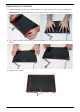


Table Of Contents
- System Specifications
- System Utilities
- Machine Disassembly and Replacement
- Disassembly Requirements
- General Information
- External Module Disassembly Process
- Main Unit Disassembly Process
- Main Unit Disassembly Flowchart
- Removing the Keyboard
- Removing the Upper Cover
- Removing the Power Switch Board
- Removing the Function Board
- Removing the USB Board
- Removing the Bluetooth Module
- Removing the LCD Module
- Removing the Mainboard
- Removing the Thermal Module
- Removing the PCH Thermal Module
- Removing the CPU
- Removing the RTC Battery
- LCD Module Disassembly Process
- LCD Module Reassembly Procedure
- Main Module Reassembly Procedure
- Replacing the RTC Battery
- Replacing the CPU
- Replacing the Thermal Module
- Replacing the PCH Thermal Module
- Replacing the LCD Module
- Replacing the Bluetooth Module
- Replacing the USB Board
- Replacing the Function Board
- Replacing the Power Switch Board
- Replacing the Upper Cover
- Replacing the Keyboard
- Replacing the ODD Module
- Replacing the Hard Disk Drive Module
- Replacing the WLAN Board
- Replacing the DIMM Modules
- Replacing the Lower Covers
- Replacing the Dummy Cards
- Replacing the Battery Pack
- Troubleshooting
- Jumper and Connector Locations
- FRU (Field Replaceable Unit) List
- Model Definition and Configuration
- Test Compatible Components
- Online Support Information
- Index

Chapter 3 87
Replacing the LCD Bezel
1. Reattach the hinges first, then press down until there are no gaps between the bezel and the LCD Module.
IMPORTANT: Ensure that the LCD cables pass through the hinge wells and are not trapped by the bezel.
2. Press down around the entire perimeter of the bezel until there are no gaps between the bezel and the LCD
Module.
3. Replace the two screws.