ULTIMATE REVERSE OSMOSIS SYSTEM INSTALLATION INSTRUCTION & OWNER’S MANUAL Ver 3.
Please keep this Owner’s Manual for future reference. It contains useful information on how to maintain and care for your APEC Reverse Osmosis water filter system. TABLE OF CONTENT 1. Installation: 2. Maintenance: 3. Owner’s Manual - RO Basics: 4. Trouble-shoot Guide: 5. Other Information: 6. Warranty ........................................................................... page 38 Preparation ................................................................... Filter housings assembly ........
Thank you for choosing APEC reverse osmosis systems. You now own the finest water filter in America. Please read and become familiar with instructions and parts needed before proceeding with the installation. (This manual is constructed for standard APEC Ultimate RO System. For RO-PH90, RO-PERM and RO-PUMP system installation, please refer to the included addendum.) BEFORE INSTALLATION: Inspect the system: Please take the system and all the components out of the box.
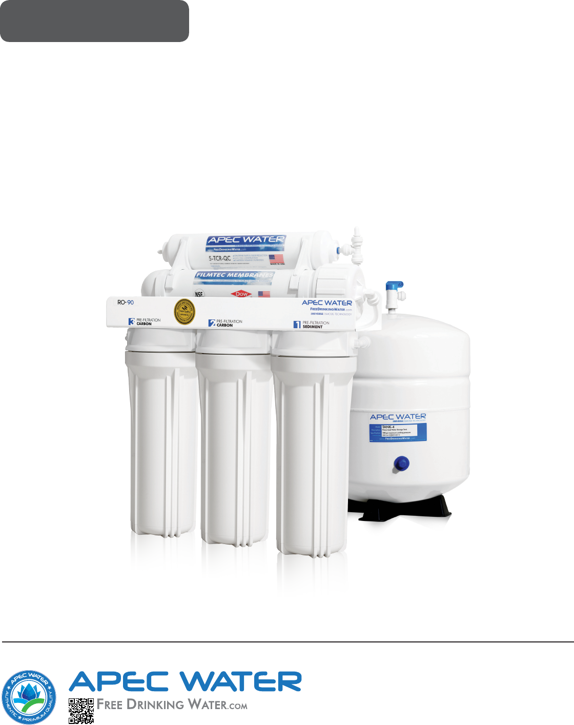
Components included with the RO system: Make sure you have all these parts before starting installation.
Component Itemization: 1) Sediment pre-filter and housing (1st-stage filter) 2) Carbon block pre-filter and housing ( 2nd-stage filter) 3) Carbon block pre-filter and housing ( 3rd-stage filter) 4) Membrane and housing (4th-stage filter) 5) In-line carbon filter (5th-stage filter) 6) Storage tank 7) Tank ball valve 8) ASO – Automatic Shut Off valve 9) Check valve (Internal check valve encased in plastic fitting) 10) T-fitting 11) Feed water inlet 12) Product (filtered) water outlet
Fitting Types: There are 2 types of fittings provided for connecting the system 1. Quick-Connect (QC) fitting: (no insert, sleeve, or nut) Most of the fittings on the RO unit are this type. Fig. 1A Fig. 1 How to Connect: - See Fig.1. Push the tubing into the Quick-Connect fitting, then gently pull back on the tubing to make sure connection was secure. - No inserts, sleeve, or nuts are needed to secure the connection. - No Teflon tape! To Disconnect: - See Fig.1A.
THERE ARE TWO PARTS TO INSTALLING THE RO SYSTEM: Part I. Part II. Assemble the filters and housings onto the main system Installing the system Note: The RO Membrane Element has already been pre installed. PART I. ASSEMBLE THE FILTERS AND HOUSINGS ONTO THE MAIN SYSTEM Remove plastic/paper wrappings on the 3 filters, put them into the 3 housings, and assemble the housings onto the main system as follow: 1. See Fig. 2 Stand the 3 housings upright. Make sure each housing has a rubber O-ring in its groove.
PART II. INSTALLING THE SYSTEM Space: Make sure there is sufficient space under the counter for installation (an area of about 17”L x 6”W x 18”H for the system, 11”D x 18”H for tank). The RO system is best installed under the kitchen sink. But if that is not feasible you can install the system anywhere where there is a cold water supply with sufficient water pressure for the chosen RO model, and an outlet to drain off the waste water from the system. Mounting: No need to mount the RO system on the wall.
Fig. 5A - Needle Valve Installation. Attach the needle valve (C) to water supply adapter (A). Please apply 5-6 wraps of teflon tape to needle valve prior to connecting it to the water supply adapter (A). Fig. 5B - If your pipe has a 1/2” Connection. By attaching the 1/2” x 3/8” converter (B) to the Male end of the water supply adapter (A), you now have a 1/2” Male and Female water supply adapter. Fig. 5C - If your pipe has a 3/8” Connection.
3. Recommend Connection For Flex Line Riser: See Fig.6A. & Fig. 6D. Loosen nut and separate cold water riser tube from faucet shank. Gently bend riser tube so that the Feed Water Adapter (Fig 5) fits onto the faucet shank. If your riser tube has no built-in washer, then fit the cone-shaped washer provided onto the riser tube. Connect the riser tube, the feed water adapter, and faucet shank together and tighten. For Solid Copper Riser: See Fig.6B. Follow the same procedure as for flex line.
Fig. 6C Fig. 6D Fig. 6E 4. Needle Valve: See Fig. 6C. Screw the Needle Valve onto the Adaptor tightly. Apply 6-8 rounds of Teflon tape onto Needle Valve before attaching it to the Adaptor. To open needle valve: To close needle valve: Turn needle handle counter-clockwise. Turn needle handle clockwise. Test for leaks at this point: Close the Needle Valve (turn needle handle clockwise all the way in to close) Turn ON the cold water supply to the sink faucet.
Step 2: Drain Saddle Installation Note: To avoid annoying drainage noise, mount drain line as low as possible on the vertical tailpiece, or on horizontal tailpiece. There is constant water pressure “packed” inside the RO system which blocks the waste water from backing-up into the system. So the waste water is “forced-drained”, not “gravity-drained”. 1. See Fig.7. The drain saddle assembly should be installed above the trap and on the vertical or horizontal tailpiece .
3. See Fig.9, 9A. Make sure to align the drain saddle hole to the drilled hole perfectly. Mis-aligning these two holes will block the waste water and cause membrane damage. Attach the drain saddle to the drain pipe and tighten the two screws evenly. Fig. 9A Step 3: Drill A Hole For The RO Faucet Drill 1/2” diameter hole for standard RO faucet. (Air-Gap faucet: drill 1&1/4” hole.) For best results use a 1/2” carbide-tipped masonry drill bit.
3. For Porcelain Sink: Porcelain enameled sinks can readily be chipped if care is not exercised when drilling the hole. Before starting the drill motor, apply firm downward pressure on the bit until a crunching occurs. This will help keep the drill bit from walking when starting the hole. A small pilot hole will also aid the drill bit. Note: Immediately after the hole drilling is done, clean up all metal chips, as metal chips will stain the porcelain!! Step 4: Mounting The Faucet 1.
Step 6: Connecting The System Summary of Tubing Connections: There are 4 connections: See Fig 11 and 11A Point A to X: Connect RO to COLD water supply — Red tubing. Point G to Y: Connect product water from 5th-stage filter to tank — Yellow tubing. This tubing is a 2-way line, Product water enters and leaves the tank via this line. Point H to Z: Connect product water from 5th-stage output to RO faucet — Clear tubing.
Fig. 11A Details on Tubing Connections: To ensure a smooth and correct installation, please connect the water lines following the sequence and order outlined below. Refer to Fig.11 & 11A for proper point locations. 1. Point Z Faucet connection: Tubing color: Fitting type: Clear tubing. Connect the CLEAR tubing to the base of the RO faucet. Quick Connect Fitting. Simply push Clear tubing into Quick Connect fitting. No Insert, Sleeve or Nut needed here.
3. Point W Waste water connection: Tubing color: Fitting type: Black tubing. Connect the BLACK tubing from the RO to the Drain Saddle. Quick-Connect fitting on drain saddle. No teflon tape. Do Not add ”insert” into Black tubing. Simply push tubing into port. 4. Point A System water inlet (to Stage 1 prefilter) connection: Tubing color: Fitting type: Red tubing. Connect the RED tubing from the Feed Water Valve to the RO’s stage -1 prefilter. Quick Connect fitting See Fig.1 on page 4.
7. Point Y Tank’s input & output connection: Prepare tank: See Fig.12. Apply 6-8 wraps of Teflon tape to tank’s threaded Output stem on top of tank (remove rubber cap if there is one). Screw tank Valve onto Output stem. Tubing color: Yellow tubing. Connect the YELLOW tubing from Stage-5 T-fitting to the tank’s valve. Fitting type: Quick-Connect fitting on ball valve. Simply push Yellow tubing into valve port. Air pressure: The 4 gallon tank comes pre charged at 5 psi, 14 gallon tank at 7 psi.
Using RO for Ice-maker only: If you want the RO to feed your ice-maker (fridge) only, you should still connect the RO faucet as a 2nd outlet. This allows you to drain the tank, flush new filters through the faucet rather than through your icemaker line. You can hang the faucet by the system and not mount it. Option: Multiple Outputs - Add Shut Off Valve: If your RO is feeding several output points (icemaker, fridge, bathroom), you should add a Shut-Off valve to each output line (except the RO spigot line).