
Specifications


FA Inspector (AOI) Scanner
69 | Page
FocalSpot, Inc. | www.FocalSpot.com
C
C
X
X
F
F
t
t
o
o
P
P
C
C
B
B
A
A
l
l
i
i
g
g
n
n
m
m
e
e
n
n
t
t
U
U
s
s
i
i
n
n
g
g
t
t
h
h
e
e
L
L
a
a
y
y
o
o
u
u
t
t
V
V
i
i
e
e
w
w
e
e
r
r
The Layout Viewer provides the ability to scan an Assembly Drawing associated with the PCB being trained.
This becomes especially useful in situations where device reference labels are not screened onto the board.
The Layout Viewer links the scanned Assembly Drawing to the inspection process which permits the developer
to view the drawing while selecting the (3) three alignment components.
NOTE: Skip this section if you have already performed CXF to PCB Alignment using REF IDs that were
screened onto the PCB or if the PCB had few enough devices to make manual identification practical.
LayoutViewerOperation
To launch the Layout Viewer:
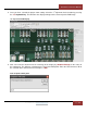
1. Press the Settings>Controls Icon <
> located in the AOI Top Menu Bar and check the Layout Viewer
checkbox. Once checked the Layout Viewer tool will open a display window.
Device Position Dialog Box Layout Viewer Tool Display
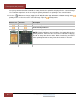
2. Next acquire an image of the Assembly Drawing either by electronic copy or by scanning a hard copy of
the drawing using the FA Inspector to scan and save an image menu options.
If you have an electronic copy of the Assembly Drawing, copy that file to a logical location on the FA
Inspector hard drive and load it into the Layout Viewer using the <Files | Load Image> menu option.
If you do not have an electronic copy of the Assembly Drawing, use the AOI Mode <Scanner |
Scanner Setup> menu option to scan the drawing. Ideally the drawing should be placed near the