
Installation Instruction

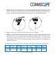


7. Notice: Observe all additional rules or restrictions regarding mounting that apply to specific
Remote Unit types. For details refer to the mechanical specifications in the data sheet for
the unit. Install the unit vertically with the fan unit at the top. A maximum tilt angle of 25°
from a vertical position must be maintained, as shown in the following illustrations:
8. Notice: A spacing of 40 mm (1.58 inch) around the unit is required.
9. Notice: To ensure sufficient airflow when mounting the unit in enclosed spaces, two lid
openings (one for the air inlet and the other for the air outlet) must be provided. Do not
block these air inlets and outlets when mounting the Remote Unit. The size of each
opening must equal at least 18 x 18 cm (> 300 cm
2
). Ensure that there is no thermal short
circuit between the air inlet and air outlet. Make sure free airflow is not deflected or
otherwise obstructed.
Specified torques must be observed for certain mounting procedures according to the following table:
Type
Tallow-drop
screws
Hex nuts
Screw band
lock
Spacing
bolts
PG
(plastic)
PG
(alum.)
Thread M 4 M 8 M 4 M 8 PG 13.5 PG 29
Specified
torques
3.3 N-m 27 N-m 6 N-m 2.3 N-m 27 N-m 3.75 N-m 10 N-m
table Specified torques