
User's Manual


4. Commissioning
MF0150A2A.doc Manual for ION-
M7P/85P/
17EP
/19P
Page 43
Spare Parts. Subminiature circular connectors series 712 with five and seven
contacts, which are contained in the alarm kit, can be ordered directly from the
Binder Connector Group, the manufacturer, or indirectly from CommScope.
For the location of the external-alarm inputs and outputs see figure “Connector
Flange”.
Optocoupler-Alarm Inputs
With the external alarm inputs it is possible to monitor the status of connected
devices, e.g. a UPS, via software. All alarm inputs are normally high (5 V) without
connection. The polarity (high/ low) can be set via the software at the Master Unit (for
details please see corresponding software manual).
Alarm Inputs:
(decoupled via optocoupler)
Input control/alarm signal/switch
contact dimensioning:
U
MAX = 5 VDC
(from Alarm Card input out)
I
MAX = 5 mA
(from Alarm Card input out)
R
(ON)MAX
= 1kΩ
(of the external switch)
│φ
GND
- φ
IN GND
│≤ 60 V
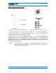
figure 4-19 Flange
connector, 5 poles
figure 4-20 Alarm inputs (optocoupler)