
Datasheet


ADM2490E
Rev. A | Page 5 of 16
REGULATORY INFORMATION
Table 5. ADM2490E Approvals
Organization Approval Type Notes
UL
Recognized under the Component Recognition
Program of Underwriters Laboratories, Inc.
In accordance with UL 1577, each ADM2490E is proof tested by
applying an insulation test voltage ≥ 6000 V rms for 1 second
(current leakage detection limit = 10 μA).
VDE
Certified according to DIN EN 60747-5-2
(VDE 0884-10 Part 2): 2003-01,
DIN EN 60950 (VDE 0805): 2001-12; EN 60950: 2000
In accordance with DIN EN 60747-5-2, each ADM2490E is proof
tested by applying an insulation test voltage ≥ 1590 V peak for
1 second (partial discharge detection limit = 5 pC).
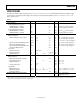
INSULATION AND SAFETY-RELATED SPECIFICATIONS
Table 6.
Parameter Symbol Value Unit Conditions
Rated Dielectric Insulation Voltage 5000 V rms 1 minute duration
Minimum External Air Gap (Clearance) L(I01) 7.45 mm min
Measured from input terminals to output
terminals, shortest distance through air
Minimum External Tracking (Creepage) L(I02) 8.1 mm min
Measured from input terminals to output
terminals, shortest distance along body
Minimum Internal Gap (Internal Clearance) 0.017 mm min Insulation distance through insulation
Tracking Resistance (Comparative Tracking Index) CTI >175 V DIN IEC 112/VDE 0303 Part 1
Isolation Group IIIa Material Group (DIN VDE 0110, 1/89)
VDE 0884-10 INSULATION CHARACTERISTICS
This isolator is suitable for basic electrical isolation only within the safety limit data. Maintenance of the safety data must be ensured by
means of protective circuits.
An asterisk (*) on a package denotes VDE 0884-10 approval for 848 V peak working voltage.
Table 7.
Description Symbol Characteristic Unit
Installation Classification per DIN VDE 0110 for Rated Mains Voltage
≤300 V rms I to IV
≤450 V rms I to II
≤600 V rms I to II
Climatic Classification 40/105/21
Pollution Degree (DIN VDE 0110, see Table 1) 2
Maximum Working Insulation Voltage V
IORM
848 V peak
Input-to-Output Test Voltage, Method b1 V
PR
1590 V peak
V
IORM
× 1.875 = V
PR
, 100% Production Tested, t
m
= 1 sec, Partial Discharge < 5 pC
Input-to-Output Test Voltage, Method a
After Environmental Tests, Subgroup 1
V
IORM
× 1.6 = V
PR
, t
m
= 60 sec, Partial Discharge < 5 pC 1357 V peak
After Input and/or Safety Test, Subgroup 2/3
V
IORM
× 1.2 = V
PR
, t
m
= 60 sec, Partial Discharge < 5 pC V
PR
1018 V peak
Highest Allowable Overvoltage (Transient Overvoltage, t
TR
= 10 sec) V
TR
6000 V peak
Safety-Limiting Values (Maximum Value Allowed in the Event of a Failure; see Figure 16)
Case Temperature T
S
150 °C
Input Current I
S, INPUT
265 mA
Output Current I
S, OUTPUT
335 mA
Insulation Resistance at T
S
, V
IO
= 500 V R
S
>10
9
Ω