
Datasheet


ADAU1381
Rev. B | Page 30 of 84
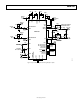
RECORD SIGNAL PATH
PGA
BEEP
PGA
LMIC/LMICN/
MICD1
LMICP
CM
PGA
RMIC/RMICN/
MICD2
RMICP
CM
DECIMATORS
LEFT
ADC
RIGHT
ADC
0
8313-029
Figure 31. Record Signal Path Diagram
INPUT SIGNAL PATH
The ADAU1381 can be configured for three types of microphone
inputs: single-ended, differential, or digital. The LMIC/LMICN/
MICD1 and RMIC/RMICN/MICD2 pins encompass all of these
configurations. LMICP and RMICP are used only during
differential configurations (see Figure 31, the record signal path
diagram).
Each analog input has individual gain controls (boost or cut). These
signals are routed to their respective right or left channel ADC.
Analog Microphone Inputs
For differential inputs, RMICN and RMICP denote the negative
and positive input for the right channel, respectively. LMICN
and LMICP denote the negative and positive input for the left
channel, respectively.
LMIC and RMIC inputs are single-ended line inputs. Together,
they can be used as a stereo single-ended input.
Digital Microphone Inputs
When a digital PDM microphone connected to the MICD1 or
MICD2 pin is used, Register 16392 (0x4008), digital microphone
and analog beep control, must be set appropriately to enable the
microphone input of choice. The MCKO output clock provides
the clock for the microphone and must be set accordingly in
Register 16384 (0x4000), clock control, depending on the
streaming PDM rate of the microphone.
The digital microphone signal bypasses the ADCs and is routed
directly into the decimation filters. The digital microphone and
ADCs share these decimation filters; therefore, both cannot be
used simultaneously.
Analog Beep Input
The BEEP pin is used for mono single-ended signals, such as a
beep warning. This signal bypasses the ADCs and the sound
engine and is mixed directly into any of the analog outputs.
n also be amplified or muted by a PGA, up
alog
400
The MICBIAS pin provides a voltage reference for electret
microphones. Register 16400 (0x4010), microphone bias
control and beep enable, sets the operation mode of this pin.
Example Configurations
A BEEP pin input ca
to 32 dB in Register 16392 (0x4008), digital microphone and an
beep control. The beep input must be enabled in Register 16
(0x4010), microphone bias control and beep enable.
Microphone Bias
TO DECIMATORS
TO DECIMATORS
PGA
LMIC/LMICN/
MICD1
LMICP
CM
PGA
RMIC/RMICN/
MICD2
RMICP
CM
0
8313-030
Figure 32. Stereo Digital Microphone Input Configuration
TO LEFT
ADC
TO RIGHT
ADC
PGA
LMIC/LMICN/
MICD1
LMICP
CM
PGA
RMIC/RMICN/
MICD2
RMICP
CM
0
8313-031
Figure 33. Single-Ended Input Configuration