
Datasheet


Data Sheet ADA4895-1/ADA4895-2
Rev. A | Page 19 of 24
APPLICATIONS INFORMATION
USING THE ADA4895-1/ADA4895-2 AT A
GAIN < +10
The ADA4895-1/ADA4895-2 are minimum gain 10 stable when
used in normal gain configurations. However, the ADA4895-1/
ADA4895-2 can be configured to work at lower gains down to a
gain of +5. Figure 50 shows how to add a simple RC circuit (R1 =
49.9 Ω and C1 = 60 pF) to allow the ADA4895-1/ADA4895-2 to
operate at a gain of +5.
V
OUT
C
L
150pF
R
O
50Ω
C1
60pF
R1
50Ω
V
IN
R
T
50Ω
R
G
50Ω
R
F
200Ω
10186-046
Figure 50. Configuring the ADA4895-1/ADA4895-2 for a Gain of +5 Stable
This circuit has a gain of +9 at high frequency and a gain of +5 at
frequencies lower than the resonance frequency of 53 MHz
(1/2πR1C1). With a noise gain of approximately +9 at high
frequency, the total output noise increases unless an antialiasing
filter is used to block the high frequency content.
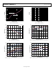
Figure 51 shows the small and large signal frequency response of
the circuit shown in Figure 50 into a 50 Ω analyzer (G = +5 V/V
or 14 dB). As shown in Figure 51, the circuit is very stable, and
the peaking is a little over 2 dB. This configuration is scalable to
accommodate any gain from +5 to +10, as shown in Table 11.
–1
2
5
8
11
14
17
0.1 1 10 100 1000
CLOSED-LOOP GAIN (dB)
FREQUENCY (MHz)
10186-047
V
OUT
= 30mV p-p
V
OUT
= 2V p-p
V
OUT
= 250mV p-p
V
S
= ±5V
G = +5
Figure 51. Frequency Response for G = +5
Table 11. Component Values Used with the ADA4895-1/ADA4895-2 for Gain < +10
Gain R
T
(Ω) R1 (Ω) C1 (pF) R
G
(Ω) R
F
(Ω) R
O
(Ω) C
L
(pF)
+5 49.9 49.9 60 49.9 200 49.9 150
+6 49.9 66.5 45 40.2 200 49.9 150
+7 49.9 110 27 37.4 226 49.9 150
+8
49.9
205
15
32.4
226
49.9
120
+9 49.9 Not applicable Not applicable 30.9 249 49.9 100