
Datasheet


AD9974
Rev. A | Page 45 of 52
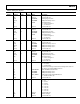
Table 27. Timing Core Registers
Address
Data Bit
Content
Default
Value Update Name Description
0x30 [5:0] 0 SCK H1POSLOC H1 Rising Edge Location.
[7:6] Unused Set unused bits to 0.
[13:8] 20 H1NEGLOC H1 Falling Edge Location.
[15:14] 0 TESTMODE Test Operation Only. Set to 0.
[16] 1 H1POL
H1 Polarity Control.
0 = inverse of Figure 21.
1 = no inversion.
[27:17] Unused Set unused bits to 0.
0x31 [5:0] 0 SCK H2POSLOC H2 Rising Edge Location.
[7:6] Unused Set unused bits to 0.
[13:8] 20 H2NEGLOC H2 Falling Edge Location.
[15:14] 0 TESTMODE Test Operation Only. Set to 0.
[16] 1 H2POL
H2 Polarity Control.
0 = inverse of Figure 21.
1 = no inversion.
[27:17] Unused Set unused bits to 0.
0x32 [5:0] 0 SCK TESTMODE Test Operation Only. Set to 0.
[7:6] Unused Set unused bits to 0.
[13:8] 20 TESTMODE Test Operation Only. Set to 20.
[15:14] 0 TESTMODE Test Operation Only. Set to 0.
[16] 1 TESTMODE Test Operation Only. Set to 1.
[27:17] Unused Set unused bits to 0.
0x33 [5:0] 0 SCK RGPOSLOC RG Rising Edge Location.
[7:6] Unused Set unused bits to 0.
[13:8] 10 RGNEGLOC RG Falling Edge Location.
[15:14] 0 TESTMODE Test Operation Only. Set to 0.
[16] 1 RGPOL
RG Polarity Control.
0 = inverse of Figure 21.
1 = no inversion.
[27:17] Unused Set unused bits to 0.
0x34 [0] 0 SCK H1BLKRETIME
Retime H1 HBLK to Internal Clock.
0 = no retime.
1 = enable retime.
Recommended setting is enable retime. Enabling retime adds one
cycle delay to programmed HBLK positions.
[1] 0 H2BLKRETIME Retime H2 HBLK to Internal Clock.
[2] 0 TESTMODE Test Operation Only. Set to 0
[3] 0 TESTMODE Test Operation Only. Set to 0
[7:4] 0 HCLK_WIDTH
Enables wide H-clocks during HBLK interval.
0 = disable (see Table 13).
[27:8] Unused Set unused bits to 0.
0x35 [2:0] 1 SCK H1DRV
H1 Drive Strength.
0 = off.
1 = 4.3 mA.
2 = 8.6 mA.
3 = 12.9 mA.
4 = 17.2 mA.
5 = 21.5 mA.
6 = 25.8 mA.
7 = 30.1 mA.
[3] Unused Set unused bits to 0.
[6:4] 1 H2DRV H2 Drive Strength.
[7] Unused Set unused bits to 0.